background image

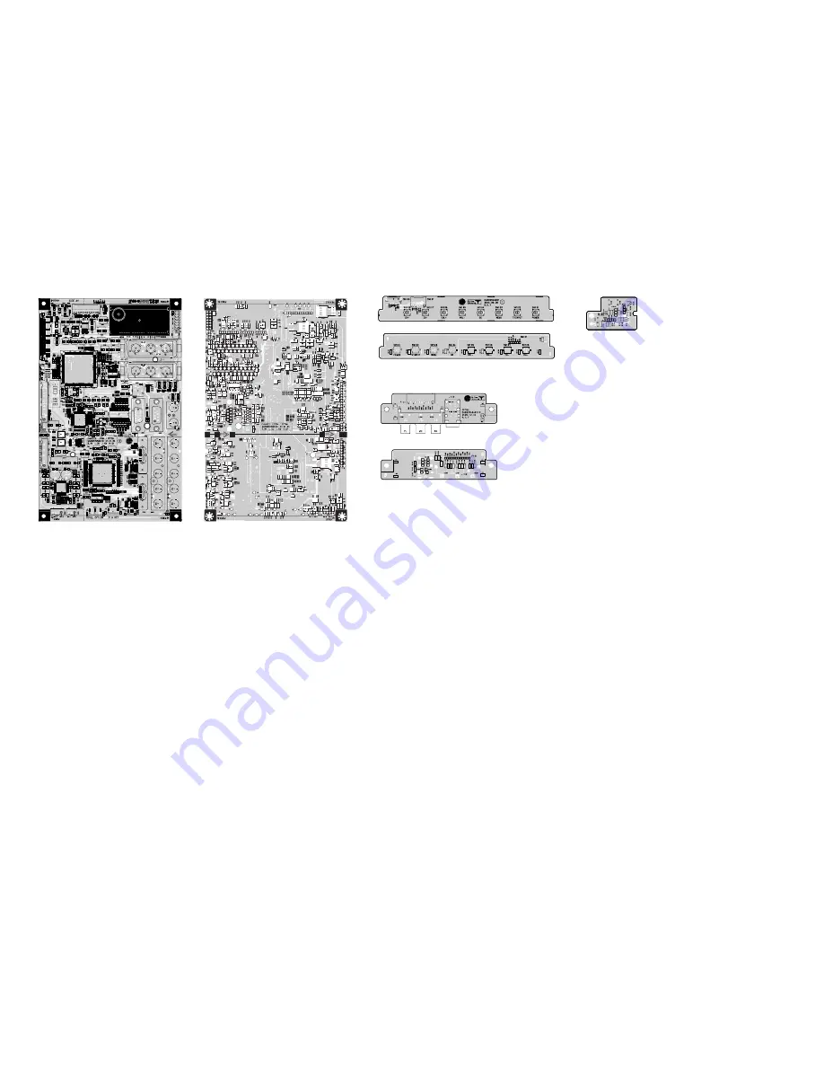
MAIN(TOP)

MAIN(BOTTOM)

SIDE A/V(TOP)

SIDE A/V(BOTTOM)

IR/LED

CONTROL(TOP)

CONTROL(BOTTOM)

PRINTED CIRCUIT BOARD

Summary of Contents for 42PC51

Page 1: ...PLASMA TV SERVICE MANUAL CAUTION BEFORE SERVICING THE CHASSIS READ THE SAFETY PRECAUTIONS IN THIS MANUAL CHASSIS PP78A MODEL 42PC51 42PC51 ZB website http biz LGservice com ...

Page 2: ...CONTENTS 2 SAFETY PRECAUTIONS 3 SPECIFICATION 4 ADJUSTMENT INSTRUCTION 6 TROUBLE SHOOTING 16 BLOCK DIAGRAM 24 EXPLODED VIEW 26 EXPLODED VIEW PARTS LIST 27 REPLACEMENT PARTS LIST 28 SVC SHEET PRINTED CIRCUIT DIAGRAM ...

Page 3: ...k With the instrument AC plug removed from AC source connect an electrical jumper across the two AC plug prongs Place the AC switch in the on position connect one lead of ohm meter to the AC plug prongs tied together and touch other ohm meter lead in turn to each exposed metallic parts such as antenna terminals phone jacks etc If the exposed metallic part has a return path to the chassis the measu...

Page 4: ...e with SBOM 5 The receiver must be operated for about 20 minutes prior to the adjustment V Test Method 1 Performance LGE TV test method followed 2 Demanded other specification Safety CE IEC specification EMC CE IEC V General Specification 42 XGA Module with 40 Display Screen Device Aspect Ratio PDP Module Operating Environment Storage Environment Input Voltage 1 2 3 4 5 6 No Item Specification Rem...

Page 5: ... 2 3 4 5 6 7 8 9 No Item Remark 1Pixel 3RGB Cells 1Pixel 3RGB Cells 5EA 1Box Remark Altitude 0 to 2000M Altitude 0 to 3000M mm mm um Kg Kg Unit deg hPa deg hPa min min Min Typ Max Unit V Module Specification2 Market Broadcasting system Available Channel Receiving system SCART Jack 2EA Video Input 1EA S Video Input 1EA Component Input 1EA RGB Input 1EA HDMI Input 1EA Audio Input 5EA Audio variable ...

Page 6: ...load the VCTP main software IC500 VCT_Pro 2 Channel memory IC501 EEPROM 3 Color carrier Adjustment 3 2 SET assembly adjustment items 1 DDC Data input 2 Adjustment of White Balance 3 Factoring Option Data input 4 PCB assembly adjustment method Using VCTP Download program 4 1 Download program installation 1 Extract a Zip file 2 Visual I2C LPT Driver Installation LPT Port Driver LptDrv Setups Program...

Page 7: ...B Ass y 1 Connect the download jig to D sub jack 2 Execute Download vi2c program in PC then a main window will be opened 3 Double click the blue box and confirm Bootloader Version as 42 4 Click the Erase Flash button 5 Double click the download file low then edit window will be opened 6 Click the choice button in the edit window then file choice window will be opened 7 Choose the Hex file in folde...

Page 8: ...te Download vi2c program in PC then a main widow will be opened 5 Double click the blue box and confirm Bootloader Version as 42 6 Click the Erase Flash button 7 Double click the download file low then edit window will be opened 8 Chick the choice button I n the edit window then file choice window will be opened 9 Click the load flash button 10 Choose the Hex file in folder and execute downloading...

Page 9: ... 4 Click GO button If you don t push the go the Hex file would not be downloaded although the download proceeds normally at first glance 5 Double click the blue box and confirm Bootloader Version as 42 6 Click the Erase Flash button 7 Double click the download file low then edit window will be opened 8 Chick the choice button I n the edit window then file choice window will be opened 9 Click the l...

Page 10: ...wnload jig 7 3 Connection structure 1 Connect the download jig to D sub jack 2 Execute Channel vi2c program in PC then a main window will be opened 7 4 Connection condition 1 IC name and circuit number VCTP and IC500 2 Use voltage 3 3V 3 SCL 15pin 4 SDA 12pin 5 Tact time about 3seconds 7 5 Download method 1 Connect the download jig to D sub jack 2 Execute Channel vi2c program in PC then a main win...

Page 11: ...od 1 tuning the RF signal ZA ZB TA TB PAL Philips Pattern with Color Bar 2 push the adj key in the adjustment remocon 10 POWER PCB Assy Voltage Adjustments Va Vs Voltage adjustments 10 1 Profile To supply the Va Vs voltage that the module want 10 2 Required Test Equipment 1 Stick for adjustment 2 DMM 10 3 Connection structure 10 4 Connection Diagram for Measuring refer to Fig 1 10 5 Adjustment Met...

Page 12: ...ing 11 4 Preparation for Adjustment 1 As above Fig 2 Connect the Set EDID Download Jig PC Cable 2 Turn on the PC EDID Download Jig And Execute the S W EDID TESTER Ver 2 5 3 Set up S W option Repeat Number 5 Device Address A0 PageByte 8 4 Power on the Set 11 5 Sequence of Adjustment 1 DDC data of Analog RGB 1 Init the data 2 Load the EDID data Open File Analog RGB PP78A_RGB ANA Digital HDMI1 PP78A_...

Page 13: ...ne 3 Month Year Controlled on production line ex Monthly 03 03 Year 2005 0F 4 Model Name model name LG TV LG TV 5 Checksum 7EH Changeable by total EDID data 1 2 3 4 4 5 1 2 4 4 3 5 1 2 3 4 4 5 5 5 1 2 3 4 4 5 10 5 1 2 3 4 4 5 5 1 2 3 4 4 5 5 20 Model Name 42PC5R 42PC51 42PC5RV 42PC7RV DEC 40079 A 40080 D 40119 A 40120 D 40121 A 40122 D Product ID HEX 9C8F 9C90 9CB7 9CB8 9CB9 9CBA EDID table 8F9C 9...

Page 14: ...the cool data Color analyzer CA110 CA210 should be used in the calibrated ch by CS 1000 PDP CH10 Operate the zero calibration of the CA 110 or CA 210 then stick sensor to the module when adjusting For manual adjustment it is also possible by the following sequence 1 Select RF no signal by pressing POWER ON key on remote control for adjustment then operate heat run more than 15 minutes If not execu...

Page 15: ... Adjust x value by decreasing the G 7 When adjustment is completed Exit adjustment mode using EXIT key on R C 13 Input the Shipping Option Data 1 Push the ADJ key in a Adjust Remote control 2 Input the Option Number that was specified in the BOM into the Shipping area 3 The work is finished Push A Key 14 Default Value in Adjustment mode Default values maybe modified the module condition 14 1 White...

Page 16: ...cord plugged in Connect the cable Plasma CN1 No Yes Are the line filter and PSU connected Replace the fuse No Yes Is the correct fuse for the PSU in place Plasma F101 Connect the 13 14pin cable Next remove all cables connected to the PSU and switch the AV voltage to manual If the ST by 5V does not operate replace the PSU No Yes Is the PSU and 13 14pin cable connected to the VSC board ...

Page 17: ...operate correctly Yes No No Is the Y Board normal Is the appropriate fuse FS2 FS3 on the Y B D Is the output voltage normal after removing the P1 connector of the Y B D Yes No No Replace the Z Board Is the Z Board normal Is appropriate fuse FS1 FS2 on the Z B D Is the output voltage normal after removing the P1 connector of the Z B D Yes No No Is the X Board normal Is the output voltage normal aft...

Page 18: ...Low High voltage except for the Stand by 5V Yes No No Is there a fault with the link cable Yes Is the output for the IC500 normal Reconnect the link cable in P803 Plasma No Replace the VSC No Yes Check the power L1103 Is the video output of the Tuner normal Check TU400_Pin13 Is the input voltage normal Check Pin3 Is the I2C communication normal Check Pin9 Pin10 Yes No Yes Is the LVDS Cable connect...

Page 19: ...nput source No 6 In the case of an unusual display in Side AV mode Is the video input of the A V jack normal Check CN703 Pin9 Yes Sam as Block A Check the input source No 7 In the case of an unusual display in Side S Video mode Is the video input of the A V jack normal Check CN703 Pin1 Pin3 Yes Sam as Block A Check the input source No ...

Page 20: ...e input source No 9 In the case of an unusual display in SCART 1_RGB mode Is the video input of the A V jack normal Check R110 R170 R171 R173 Yes Sam as Block A Check the input source No 10 In the case of an unusual display in SCART 2 mode Is the video input of the A V jack normal Check R174 Yes Sam as Block A Check the input source No ...

Page 21: ...put source No 12 In the case of an unusual display in component 2 mode Yes Change IC IC500 Check the input source No Is the video input of the A V Jk202 normal Check R241 R242 R243 13 In the case of an unusual display in RGB mode Yes Change IC IC500 Check the input source No Is the R G B input and H V sync of the JK201 normal Check R220 R221 R253 R254 R255 ...

Page 22: ...ere no sound only AV COM2 PC Is the output of IC600 R607 R608 normal Yes Is there no sound only for RF No No No No Download the EDID data Set speaker on in the menu No Replace the IC600 No Check the Speaker cable No Is the IC500 operating normal Replace the IC500 No Yes Is the IC601 operating normal Replace the IC601 Replace the VSC BD Yes Check the signal after IC600 refer to circuit diagram Chec...

Page 23: ...thentication attempted Reset TMDS power down on register 0x60 offset 0x3f 0xff Check HDMI source Change to another source or cable Yes Is the wave continuous Normal video Normal audio No Yes Replace the IC303 No 1 Check TV input mode HDMI 1 port support HDMI and DVI So if you input DVI signal and PC audio from phone jack You can hear PC audio 2 Unplug and plug in the HDMI cable sometimes ESD surge...

Page 24: ...OUT HEAD_OUT L R COMP2_R L HS VS PIP OPTION ANX9021 ANX9021 TMDS RECIEVER TMDS RECIEVER TEA6420 Sound switch 2 RX 0 1 2 CLK SIDE_R L SCART1 2_V RCA1 2_V EEPROM EEPROM SUB TUNER VIDEO_DECODER TW9909 TW9909 EEPROM EEPROM VCT Pro Lip sync SCART_FB AV_AUDIO R L AM_AUDIO COMP1_R L I 2 C RX 0 1 2 CLK TV_OUT TV_OUT MNT_OUT MNT_OUT PIP_V ITU 656_IN SCART1 2_I D HDMI_Y Pb Pr 1080P SCART_RGB STMAV335 MUX RT...

Page 25: ...MEMO 25 ...

Page 26: ... 26 EXPLODED VIEW 300 120 304 560 570 600 306 301 302 303 400 240 250 200 206 580 205 202 203 204 201 900 901 501 590 520 502 603 601 602 ...

Page 27: ...ACKET SPEAKER DIRECT GRILL 400 ACQ31583501 Cover Assembly Rear 42PC5 42 BACK COVER ASSY ANALOG SMALL LGERA ACQ31583504 Cover Assembly Rear 42 LGEMA PHANTOM 501 AGU31681101 Plate Assembly ASSY PLATE TUNER BOT SMALL 42PC5 LGERA AGU31681115 Plate Assembly ASSY PLATE TUNER BOT SMALL 42PC5R ZB MA LCOAL 502 AGU31680901 Plate Assembly ASSY PLATE TUNER COVER SMALL 42PC5 LGERA AGU31680921 Plate Assembly AS...

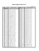
Page 28: ...0uF 20 25V 2 C312 0CK103CK51A 0603B103K500CT 10nF 10 50V Y5P C316 0CE106WFKDC MVK4 0TP16VC10M 10uF 20 16V 16MA C317 0CK103CK56A 0603B103K500CT 10nF 10 50V X7R C318 0CE106SH6DC VMV106M025S0ANB010 10uF 20 25V 2 C319 0CK103CK56A 0603B103K500CT 10nF 10 50V X7R C320 0CC220CK41A C1608C0G1H220JT 22pF 5 50V C0G C321 0CC220CK41A C1608C0G1H220JT 22pF 5 50V C0G C322 0CC220CK41A C1608C0G1H220JT 22pF 5 50V C0G...

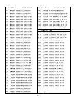
Page 29: ...6X5R1C475MT 4 7uF 20 16V X5R C617 0CK475EF67A C3216X5R1C475MT 4 7uF 20 16V X5R C618 0CK475EF67A C3216X5R1C475MT 4 7uF 20 16V X5R C619 0CK102CK56A 0603B102K500CT 1nF 10 50V X7R 5 C620 0CK102CK56A 0603B102K500CT 1nF 10 50V X7R 5 C621 0CK682CK51A C1608Y5P1H682KT 6 8nF 10 50V Y5P C622 0CK682CK51A C1608Y5P1H682KT 6 8nF 10 50V Y5P C623 0CC270CK41A C1608C0G1H270JT 27pF 5 50V C0G C624 0CK105DK94A 0805F105...

Page 30: ...45901 CDS3C30GTH 30V 50V 120V 1 9A 1W S D204 EAH33945901 CDS3C30GTH 30V 50V 120V 1 9A 1W S D205 EAH33945901 CDS3C30GTH 30V 50V 120V 1 9A 1W S D206 EAH33945901 CDS3C30GTH 30V 50V 120V 1 9A 1W S D207 EAH33945901 CDS3C30GTH 30V 50V 120V 1 9A 1W S D208 EAH33945901 CDS3C30GTH 30V 50V 120V 1 9A 1W S D208 0DR050008AA SD05 TC 6V 14 5V 24A 350W SOD32 D209 EAH33945901 CDS3C30GTH 30V 50V 120V 1 9A 1W S D209 ...

Page 31: ...0TCE001G HH 1M3216 501JT 500OHM 3 2X1 6X1 L802 6210TCE001B HH 1H3216 500JT 50OHM 3 2X1 6X1 3 L803 6210TCE001G HH 1M3216 501JT 500OHM 3 2X1 6X1 L806 6210TCE001G HH 1M3216 501JT 500OHM 3 2X1 6X1 L807 6210TCE001G HH 1M3216 501JT 500OHM 3 2X1 6X1 L808 6210TCE001G HH 1M3216 501JT 500OHM 3 2X1 6X1 X300 6202TST001H Crystal SX 1 27MHZ 30PPM 27MHZ 30PPM 20pF X500 6202VDT002P Crystal HC 49 SM 20 25000MHZ 20...

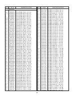
Page 32: ... 160 R140 0RJ4701D677 MCR03EZPJ472 4 7KOHM 5 1 10W 160 R141 0RJ4701D677 MCR03EZPJ472 4 7KOHM 5 1 10W 160 R153 0RJ0000D677 MCR03EZPJ000 0OHM 5 1 10W 1608 R R154 0RJ0752D677 MCR03EZPJ750 75OHM 5 1 10W 1608 R155 0RJ0000D677 MCR03EZPJ000 0OHM 5 1 10W 1608 R R156 0RJ0000D677 MCR03EZPJ000 0OHM 5 1 10W 1608 R R157 0RJ9101D677 MCR03EZPJ912 9 1KOHM 5 1 10W 160 R158 0RJ0752D677 MCR03EZPJ750 75OHM 5 1 10W 16...

Page 33: ...10W 1608 R336 0RJ1000D677 MCR03EZPJ101 100OHM 5 1 10W 1608 R337 0RJ1000D677 MCR03EZPJ101 100OHM 5 1 10W 1608 R338 0RJ0222D677 MCR03EZPJ220 22OHM 5 1 10W 1608 R338 0RJ0682D677 MCR03EZPJ680 68OHM 5 1 10W 1608 R339 0RJ0222D677 MCR03EZPJ220 22OHM 5 1 10W 1608 R339 0RJ0682D677 MCR03EZPJ680 68OHM 5 1 10W 1608 R340 0RJ0222D677 MCR03EZPJ220 22OHM 5 1 10W 1608 R340 0RJ0682D677 MCR03EZPJ680 68OHM 5 1 10W 16...

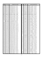
Page 34: ...470OHM 5 1 10W 1608 R567 0RJ1001D677 MCR03EZPJ102 1KOHM 5 1 10W 1608 R570 0RJ0000D677 MCR03EZPJ000 0OHM 5 1 10W 1608 R R573 0RJ2702D677 MCR03EZPJ273 27KOHM 5 1 10W 1608 R575 0RJ4701D677 MCR03EZPJ472 4 7KOHM 5 1 10W 160 R6 0RH0000D622 MCR10EZHJ000 0OHM 5 1 8W 2012 R R6 0RH0000D622 MCR10EZHJ000 0OHM 5 1 8W 2012 R R600 0RJ1001D677 MCR03EZPJ102 1KOHM 5 1 10W 1608 R601 0RJ1001D677 MCR03EZPJ102 1KOHM 5 ...

Page 35: ...0 8P 1 25MM 1R STRAIGHT CN703 6602T20009L Wafer SMAW200 12P 12P 2 00MM 1R ANGLE D CN800 6602T25008N Wafer SMW250 14P 14P 2 50MM 1R STRAIGHT CN801 6602T25008J Wafer SMW250 10P 10P 2 50MM 1R ANGLE DI P100 6602T20009E Wafer SMAW200 06P 6P 2 00MM 1R ANGLE DI P101 6602T20009L Wafer SMAW200 12P 12P 2 00MM 1R ANGLE D JK201 6630G70016A DSUB A03 7071 094 D SUB 15P 2 29MM STR JK100 6612J10033A PMJ016 13 13P...

Page 36: ......

Page 37: ......

Page 38: ......

Page 39: ...MAIN TOP MAIN BOTTOM SIDE A V TOP SIDE A V BOTTOM IR LED CONTROL TOP CONTROL BOTTOM PRINTED CIRCUIT BOARD ...

Page 40: ...Mar 2007 Printed in Korea P NO MFL38559902 ...

Reviews: