- 13 -
LGE Internal Use Only
Copyright©2008 LG Electronics. Inc. All right reserved.
Only for training and service purposes
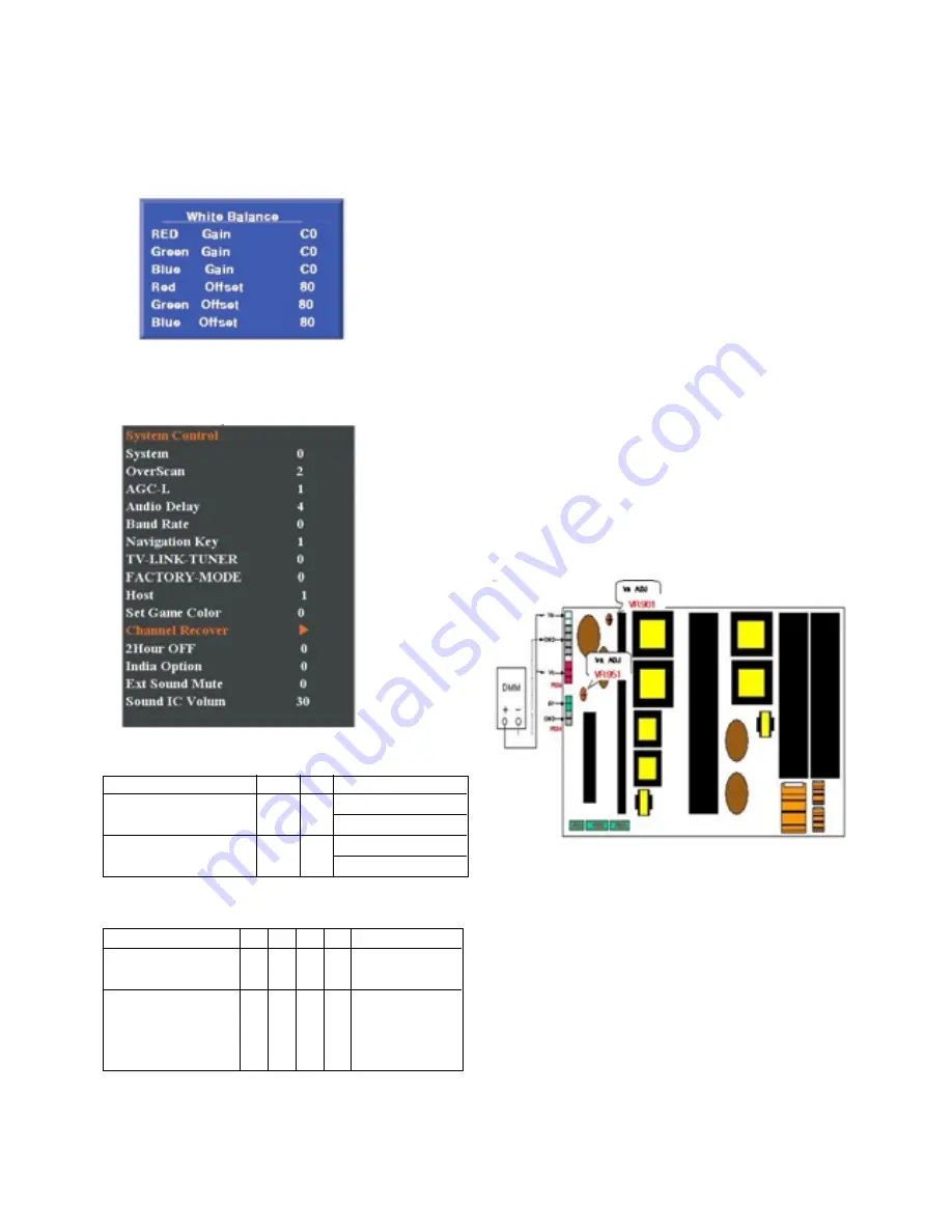
10. Default Value in Adjustment
10-1. White Balance
(Default values maybe modified the module condition)
10-2. Press CH write condition
(1) AC on tilme on only one after assembled automatically
(2) CH recover SVC OSD manually
11. Internal press test
12. Sound spec.
Caution: Each PCB assembly must be checked by check JIG set.
(Because power PCB Assembly damages to PDP
Module, especially be careful)
13. POWER PCB Assy Voltage
Adjustment
(Va, Vs voltage Adjustment)
13-1. Test Equipment:
D.M.M 1EA
13-2. Connection Diagram for Measuring
Refer to Fig. 5
13-3. Adjustment Method
(1) Va Adjustment
1) After receiving 100% Full White Pattern, HEAT RUN.
2) C terminal of D. M..M. to Va pin of P812,
connect -terminal to GND pin of P812.
3) After turning VR901,voltage of D.M.M adjustment as
same as Va voltage which on label of panel right/top
(deviation; ±0.5V)
(2) Vs Adjustment
1) C terminal of D. M..M. to Vs pin of P812,
connect -terminal to GND pin of P812.
2) After turning VR951 401, voltage of D.M.M adjustment
as same as Vs voltage which on label of panel right/top
( deviation ; ±0.5V)
<Fig. 5> Connection Diagram of Power Adjustment for Measuring
Item
Dielectric Voltage (AC <-> FG)
Dielectric Voltage (Without FG)
Value
1.5
1.5
3
3
Unit
kV
kV
Remark
At 100mA for 1sec (Line)
At 100mA for 1min (OQC)
At 100mA for 1sec (Line)
At 100mA for 1min (OQC)
Typ
Min
Max Unit
Remark
Item
Audio Practical Max Output,
L(Mono)/R
Audio Practical Max Output,
L(Mono)/R
9
13
10
15
12
17
W
W
42/50PG21-TA,
42/50PG61UR-TA
Support 15W Sound
output (6Ohm)


