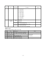
(4) Using the Service Remote Control, enter from ADJ to
Actuator_50Hz.
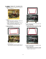
(5) ACT Gain and Phase is variable and the Tartan plaid of R,
G, B, W Horizontal Line adjust not distinguished not to be.
a. The Phase(Base value : 180) variable adjust
Mutation point of Actuator.
b. The Gain(Base value : 50) adjust mutation quantity of
Actuator.
*
The Tartan plaid of R, G, and B adjust not visible not to
be. But, when the R, G and B will not agree, adjust with
point R and G agree.
14. CWI / NDC Adjustment
(Base value --> CWI: 160, NDC: 12)
1) Required Test Equipment
: Remote control
2) Preparation for Adjustment
(1) Connect power and turn Power on.
(2) Using the Remote Control, enter from ADJ to CWI/ NDC.
3) Adjustment
(1) Using the Channel key, adjust CWI-Pat.1 to the LEFT/
RIGHT
(2) As adjustment, check the appearance noise in the
TEST Pattern<Fig 18>.
Setting the value reduced (3)~(4) step at a GREEN noise
disappearing spot.
* Intermediate value the point Green color disappears from
the Ramp Pattern and the point bottom color purity
comes to be uniform from the RED Pattern is same
(3)~(4)-step with value Green color disappears from the
Ramp Pattern.
(3) Using CH UP/DOWN key of the Remote Control, enter
the RED PATTERN.
(4) Check the RED Pattern<Fig 19> to uniform. After
checking unless abnormality do OK.
4) NDC Adjustment
For compensation deviation of each Lamp uses NDC
Mode.Sees the Pattern and adjust left/right value using
Channel Key on Remote Control for Adjustment to be
uniform color of the White. (Lamp life compensation)
* As temperature is different sensitivity, change angle of the
color wheel. At this time, the adjustment is done because
color may be changed.
15.
Adjusting the Auto CCA
1) Required Test Equipment
: CA-210
2) Adjustment Sequence
(1) Install the equipment(CA210) be 5cm away from screen
center.
(2) RS-232C cable is connected from Control PC in the SET.
(3) Measure is started in the statement that SET is done to
Heat Run.
- 23 -
<Fig 16. Test Pattern>
Before Actuator Adjustment
After Actuator Adjustment
<Fig 17. Test Pattern>
Before Actuator Adjustment
After Actuator Adjustment
<Fig 18. Test Pattern>
<Fig 19. RED Test Pattern>
<Fig 20. Test Pattern>
Summary of Contents for 44/52SZ8R
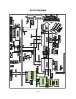
Page 26: ... 26 BLOCK DIAGRAM ...
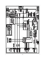
Page 27: ... 27 ...
Page 28: ... 28 ...
Page 29: ... 29 ...
Page 30: ... 30 ...
Page 31: ... 31 ...
Page 48: ......
Page 49: ......
Page 50: ......


