- 13 -
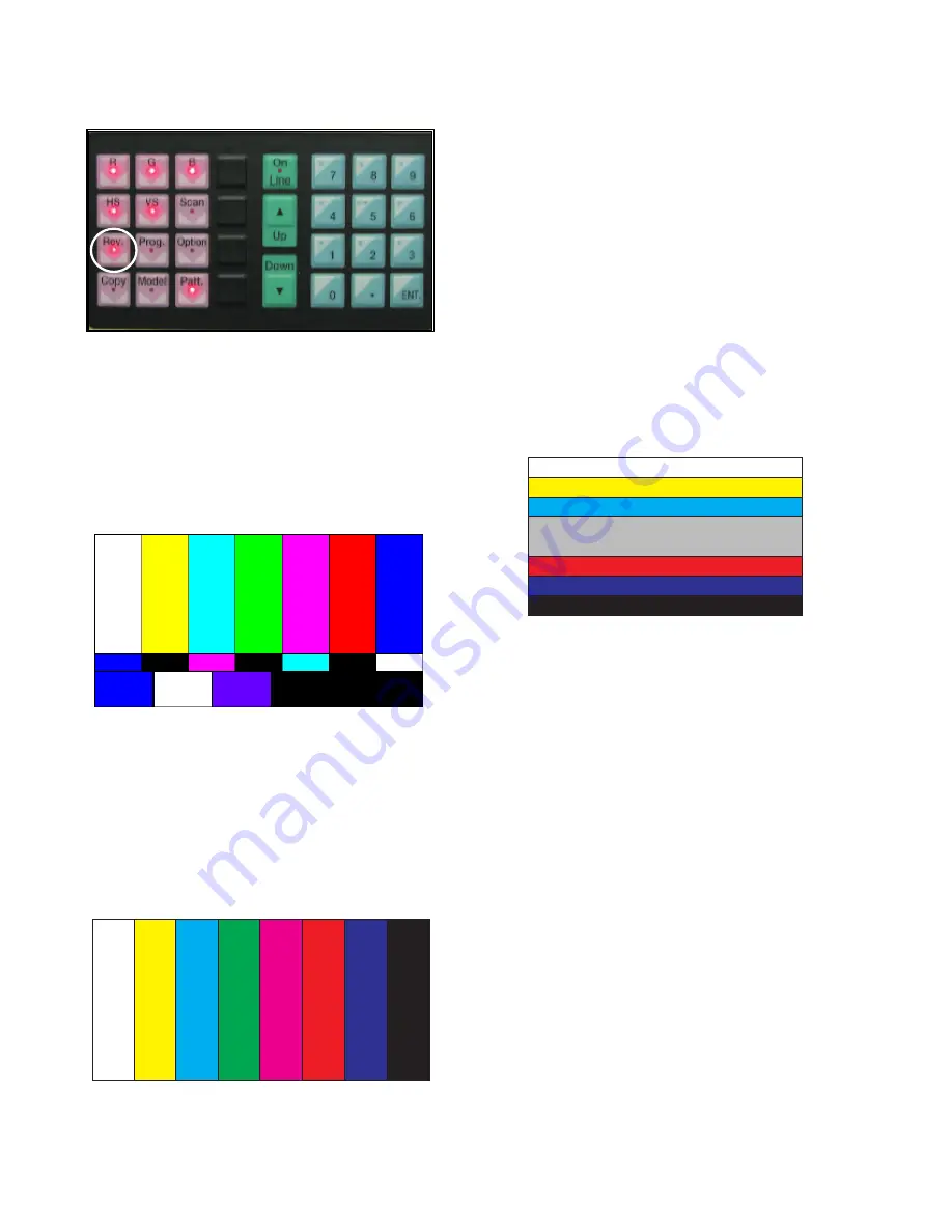
In this case, first press the
Rev button
of Video Signal
Generator (Master), to generate the white pattern to be displayed
from the left.
Because the above pattern can differ by the model and pattern
for each device, you must check the pattern first.
B. When the receiving signal is confirmed after inputting the
internal signal, press the ADJ KEY on the adjustment R/C
to enter ‘EZ-ADJUST’. Select ‘5.Adjust RF and Video’ and
press the right key (
G
) to enter the adjustment mode.
C. When you enter the adjustment mode, the video is
automatically set to TV 2CH and the following window is
displayed.
D. When the adjustment is completed, a message saying ‘RF
Configuration Success’ is displayed. If the adjustment has
failed, a message saying ‘RF Configuration Error’ is
displayed.
E. When the automatic adjustment of RF signal is completed,
it is automatically switched to the Video Mode as shown in
the above picture, and automatic adjustment for Video
Mode is done. When the automatic adjustment is
completed, a message saying ‘Video Configuration
Success’ is displayed. If the adjustment has failed, a
message saying ‘Video Configuration Error’ is displayed..
O
Check RS-232C operation
Press the Instart of adjustment R/C to enter the 7.Baud Rate
menu and set the Baud Rate to 115200 to check the 232-C
operation
5. Automatic adjustment of Component
480i/1080p RGB 1080p
5.1 Introduction
The Component 480i/1080p RGB 1080p adjustment sets the
optimal black level and gain automatically from the analog =>
digital converter, and is the function to correct the RGB
deviation
5.2 Using device
Adjustment remote controller, 801GF (802B, 802F, 802R) or
MSPG925FA Pattern Generator
(480i/1080P Horizontal 100% Color Bar Pattern output must
be possible and output level must be adjusted accurately to
0.7±0.1Vp-p.)
Because the above pattern can differ by the model and pattern
for each device, you must check the pattern first.
(Adjustment pattern : 480i / 1080P 60Hz Pattern)


