- 16 -
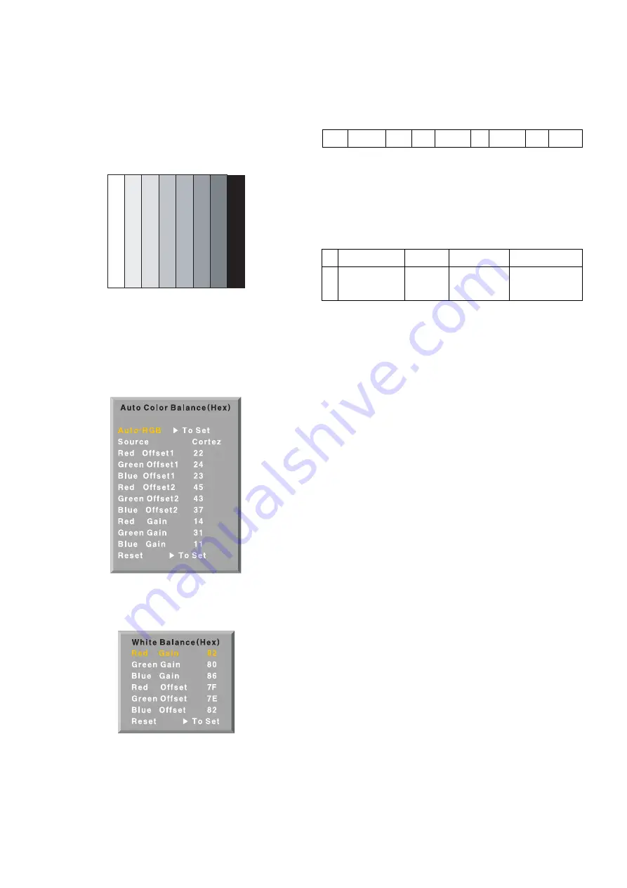
11-3. Method of Auto RGB Color Balance
1) Input the PC 1024x768 60Hz 100%Color bar into RGB.
2) Set the PSM to Standard mode in Picture menu.
3) Press ADJ key on R/C for adjustment.
4) Press the
G
(Vol. +) key operate To set, then it becomes
automatically.
5) Auto-RGB OK means completed adjustment.
12. Default value in adjustment mode
( Default valued maybe modified during E/S & L/P Event for
adjustment time reduction, but will be fixed beforeMass Production.)
12-1. Auto Color Balance (Component/RGB)
12-2. White Balance
13. EEPROM Data Write
13-1. Signal TABLE
CMD
: A0h
LENGTH : 85~94h (1~16 bytes)
ADH
: E2PROM Sub Address high (00~1F)
ADL
: E2PROM Sub Address low (00~FF)
Data
: Write data
CS
: CMD + ADH + ADL + ... + Data_n
Delay
: 20ms
13-2. Command Set
* Description
FOS Default write : <7mode data> write
Vtotal, V_Frequency, Sync_Polarity, Htotal, Hstart, Vstart, 0, Phase
Data write : Model Name and Serial Number write in EEPROM,.
13-3. Method & notice
1) Serial number D/L is using of scan equipment.
2) Setting of scan equipment operated by Manufacturing
Technology Group.
3) Press FRONT-AV on control R/C before Serial number D/L.
4) Serial number D/L must be conformed when it is produced
in production line, because serial number D/L is mandatory
by D-book 4.0.
(Fig. 13) Default Value on OSD
(Fig. 12) Default Value on OSD
(Fig. 11) Auto RGB Color Balance Test Pattern
CMD LENGTH ADH ADL DATA_1
DATA_N
...
CS
DELAY
No
1
EEPROM WRITE A0h
84h+n
n-byted Write
(n=1~16)
Adjust mode
CMD(hex) LENGTH(hex)
Description
Summary of Contents for 50PC1DA Series
Page 23: ...MEMO 23 ...
Page 52: ...MAIN Control Pre AMP ...
Page 53: ......
Page 54: ...PRINTED CIRCUIT BOARD MAIN TOP MAIN BOTTOM AV TOP AV BOTTOM CONTROL PRE AMP SIDE A V ...


