background image

- 11 -

Copyright©2008 LG Electronics. Inc. All right reserved. 
Only for training and service purposes

LGE Internal Use Only

TROUBLE SHOOTING GUIDE

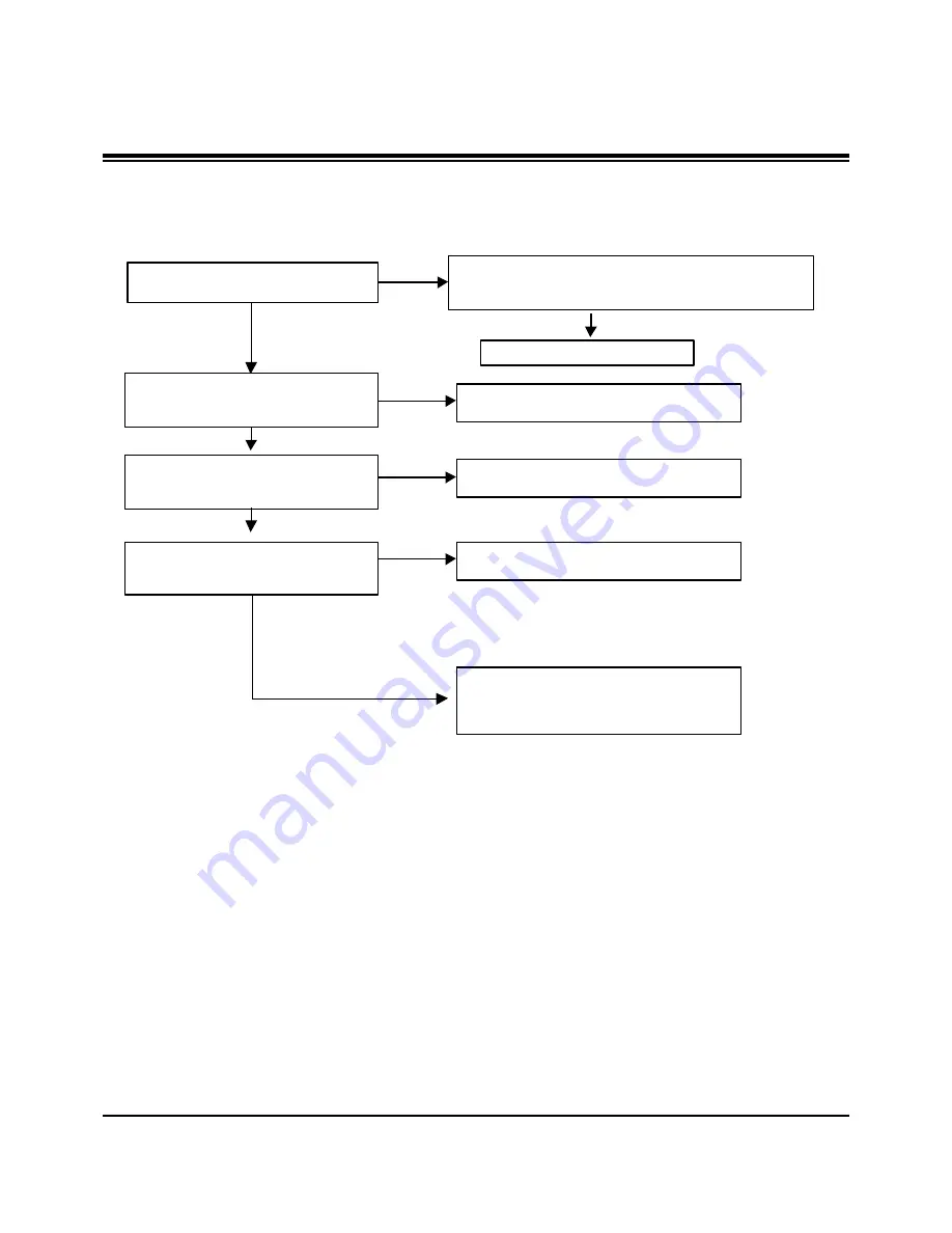
TV/CATV(Analog ) doesn t display

Check TU1 Pin16(Video output)

Can you see the normal signal?

Check the input(Pin1) of Low-Pass Filter

(IC808).

Can you see the normal waveform?

Check the output(pin8) of Low-Pass

Filter(IC808).

Can you see the normal waveform?

Check the Capaciter(C658) in front of

BCM3553 chip.

Can you see the normal waveform?

YES

YES

YES

NO

Could you measure VCC voltage(3Pin) of TU1 & IIC

lines(7,8Pin)?

Are they all normal?

YES

You should replace TUNER.

NO

After checking the C800(0.1uF Cap), you can

suspect  that PCB is bad.

NO

After checking the Power of Low-Pass Filter you

should decide to replace Low-Pass Filter or not.

NO

After checking the pattern between pin8 of IC808

and C658,  you can suspect that PCB is bad..

YES

This board has big problem because Main

chip(BCM3550) have some troubles.

After checking thoroughly all path once again,

You should decide to replace BCM3553 or not.

Summary of Contents for 50PG60 Series

Page 1: ...N BEFORE SERVICING THE CHASSIS READ THE SAFETY PRECAUTIONS IN THIS MANUAL CHASSIS PU82C MODEL 60PG60 60PG60F UA CANADA http biz lgservice com USA http www lgservice com http biz lgservice com Internal Use Only CH VOL MENU INPUT ENTER ...

Page 2: ... switch in the on positioin connect one lead of ohm meter to the AC plug prongs tied together and touch other ohm meter lead in turn to each exposed metallic parts such as antenna terminals phone jacks etc If the exposed metallic part has a return path to the chassis the measured resistance should be between 1MΩ and 5 2MΩ When the exposed metal has no return path to the chassis the reading must be...

Page 3: ...ved Only for training and service purposes LGE Internal Use Only SPECIFICATIONS 4 ADJUSTMENT INSTRUCTIONS 5 TROUBLE SHOOTING GUIDE 11 BLOCK DIAGRAM 16 EXPLODED VIEW 24 EXPLODED VIEW PARTS LIST 25 SCHEMATIC DIAGRAM PRINTED CIRCUIT BOARDS TABLE OF CONTENTS ...

Page 4: ...xternal Antenna Impedance Environment condition With stand Without stand With stand Without stand Operating Temperature Operating Humidity Storage Temperature Storage Humidity 42PG60 42PG60 UA 50PG60 50PG60F UA 60PG60 60PG60F UA 41 1 x 28 9 x 12 1 inches 1044 4 x 735 4 x 308 0 mm 41 1 x 26 7 x 3 1 inches 1044 4 x 680 6 x 79 6 mm 61 7 pounds 28 0 kg 55 1 pounds 25 0 kg 48 6 x 33 4x 14 3 inches 1235...

Page 5: ...into White Pattern Press POWER ON Key on the Service Remote Control S R C Enter the Ez Adjust by pressing ADJ Key on the Service Remote Control S R C Select 10 Test Pattern using the CH Key and select the White by pressing the direction Key Display the 100 Full White Pattern Set is activated HEAT RUN without signal generator in this mode O HEAT RUN Preliminary action is applied to the test for aft...

Page 6: ...of P12 and connect terminal to GND pin of P12 2 Adjust VR951 voltage to match that of the label on the Top Right of the panel Deviation 0 5V 2 Vs Adjustment 1 Connect terminal of D M M to Vs pin of P12 and connect terminal to GND pin of P12 2 Adjust VR901 voltage to match that of the label on the Top Right of the panel Deviation 0 5V 3 4 Adjustment 42 1 Va Voltage Adjustment 1 Connect terminal of ...

Page 7: ...ontal Color Bar Pattern HozTV31Bar in 1080p Mode and select Normal in screen 3 After receiving signal for at least 1 second press the ADJ Key on the Service R C to enter the Ez Adjust and select the 4 ADC 1080p Comp1 RGB Pressing the Enter Key to adjust automatically component1 4 When the adjustment is over ADC Component1 Success is displayed If the adjustment has errors ADC Component1 1080p Fail ...

Page 8: ...vice purposes LGE Internal Use Only ADJUSTMENT INSTRUCTIONS 5 2 EDID DATA for PU82C EDID for HDMI 1 DDC Display Data Channel Data EDID table EDID for HDMI 2 DDC Display Data Channel Data EDID table EDID for HDMI 3 DDC Display Data Channel Data EDID table EDID DATA for RGB EDID table ...

Page 9: ...when internal pattern is not possible you can select HDMI input for adjustment Through the option at the most bottom part of the Ez Adjust Menu 7 White Balance menu you can select NONE INNER and HDMI and the default is set to INNER When the adjustment cannot be done with the internal pattern you can select HDMI input for adjustment For manual adjustment press the ADJ KEY of the adjustment R C to e...

Page 10: ...nutes 4 Execute a Zero Calibration for CA 210 and put it at distance of less than 10Cm from the PDP module surface center during the adjustment 5 Select 7 White Balance of Ez Adjust by pressing the ADJ KEY on the Service R C Then enter adjustment mode by pressing the Right KEY G The internal pattern of full white appears by pressing G 6 The adjustment is conducted in three levels of color temperat...

Page 11: ...658 in front of BCM3553 chip Can you see the normal waveform YES YES YES NO Could you measure VCC voltage 3Pin of TU1 IIC lines 7 8Pin Are they all normal YES You should replace TUNER NO After checking the C800 0 1uF Cap you can suspect that PCB is bad NO After checking the Power of Low Pass Filter you should decide to replace Low Pass Filter or not NO After checking the pattern between pin8 of IC...

Page 12: ...R732 Can you see the normal waveform YES YES NO JK701 may have problem Replace this Jack Check the C651 in front of BCM3553 chip Can you see the normal waveform NO replace Part R732 YES This board has big problem because Main chip BCM3553 have some troubles After checking thoroughly all path once again You should decide to replace BCM3553 or not NO After check the pattern between R703 and C651 You...

Page 13: ... Can you see the normal waveform Check the C638 C628 in front of BCM3553 Can you see the normal waveform YES YES NO JK700 JK702 may have problem Replace this Jack NO Replace the Part L700 L704 NO After check the pattern between L703 and C651 You can suspect that PCB is bad YES This board has big problem because Main chip BCM3553 have some troubles After checking thoroughly all path once again You ...

Page 14: ...see the normal waveform YES NO JK705 may have problem Replace this Jack NO After check the pattern between input of BCM3553 and JK705 You can suspect that PCB is bad RGB_PC doesn t display Check JP7029 JP7030 Can you see the normal waveform YES NO JK705 may have problem Replace this Jack YES This board has big problem because Main chip BCM3553 have some troubles After checking thoroughly all path ...

Page 15: ...BCM3553 Especially you should check The H V sync and clock Can you see the normal waveform YES NO NO After checking the trace of TMDS lines and power of PI3HDMI341ART IC703 TMDS141RHAR HDMI4 you should decide to replace PI3HDMI341ART IC703 TMDS141RHAR HDMI4 or not NO YES This board has big problem because Main chip BCM3550 have some troubles After checking thoroughly all path once again You should...

Page 16: ... CVBS Y Pb Pr R G B H V Sync RGB PC HDMI 0 1 2 COMP 1 COMP 2 AV 1 AV 2 RGB PC Audio L R I2S MNT out L R SPDIF OUT I2S RS 232C Dead IC when Standby Option Alive IC when Standby Video Audio Video Front End Dual HDMI Rx HD SD Video Encoder Audio DSP BCM3552 HD 3 FHD MCLK MCLK HDMI CEC HDMI CEC To Micom To Micom SDA SCL SIF IF AT Buffer Single Channel Digital out W XGA Local KEY IR Buffer Buffer 24C16...

Page 17: ... Y C CVBS CVBS 2 L1 C1 CVBS 3 L2 C2 ANT Cable TUNER IF_P IF_N IF_P from TUNER for DTV IF_N from TUNER for DTV CVBS 1 EEPROM FOR EDID DDC SDA DDC SCL RGB V_Sync LVDS_Tx Out Component_1 S W Component_2 S W Rear_CVBS_ S W RGB S W GPIO 0 6 Comp2_Y Comp2_Pb Comp2_Pr RGB_G RGB_B RGB_R DDC SCL to Micom for Download LPF 6 Mhz LPF 30Mhz LPF 30Mhz LPF 30Mhz LPF 30Mhz LPF 30Mhz LPF 30Mhz LPF 6 Mhz LPF 6 Mhz ...

Page 18: ...DS1 INPUT TMDS2 INPUT TMDS RX0 TMDS RX1 TMDS RX2 TMDS RXCLK Hot Plug Detect_0 TMDS Out TMDS_Rx Input0 HDMi_Sel_0 HDMi_Sel_1 HDMi_Sel_2 Hot Plug Detect_1 Hot Plug Detect_2 5V Power_0 5V Power_1 5V Power_2 GPIO 0 8 Switch Selection DDC INPUT MTV416 Micom HDMi CEC Parallel connections with HDMi 0 1 2 4 LVDS out 31P Con 31P LVDS Con EEPROM for HDCP DDC SDA1 DDC SCL1 DDC SDA2 DDC SCL2 TMDS0 RX0 TMDS0 R...

Page 19: ...Buffer PWM MODULATOR POWER AMP NTP3000A SIF IN Broadcom BCM3552 3 AUD_SPDIF ANA L R IN BCM_MCLK BCM_MCLK I2S_CLK_IN I2S_DATA_IN I2S_LR_IN RESET RESET I2S_CLK_OUT I2S_DATA_OUT I2S_LR_OUT NTP3000A I2S_CLK_OUT DATA_OUT LRCH OUT I2C SCL SDA OUT1A B OUT2A B SPK R SPK L MNT_L R OUT HDMI Rx Built in Internal I2S SPDIF Convert HDMI_TMDS 0 1 2 3CLK TUNER ATSC NTSC I2C SCL SDA Buffer Buffer SIF IF_P IF_N AU...

Page 20: ...nternal Use Only BLOCK DIAGRAM BCM3553 4 7K 5 0V I2C_Channel 0 I2C_Channel 1 ATSC NTSC Tuner I2C_Channel 2 I2C_Channel 3 I2C0_5V I2C1_5V 4 7K 5 0V Address 0xC2 0x9A 0x74 0xA6 0x94 0x54 0x50 0x 0xD4 0x I2C MAP HDCP Key EEPROM NTP3000 NVRAM I2C2_3 3V I2C3_3 3V MTV416 4 7K 3 3VST 1K 3 3V CS5345 PDP MODULE ...

Page 21: ... 12 0V 9V IC811 KA7809 IC803 KIA78R05F 5V_TUNER TU1 TDVF H051F ST_5V ST_5V Local key IR power IC202 ICL3232 RS 232C RX TX Q804 SI4925BDY IC102 AT24C16AN EEPROM 5 0 IC407 MTV416GMF micom HDMI CEC Inv RL 3 3V 5V Q805 SI4925BDY IC408 Comercial IC404 3 3V_MICOM IC402 RS232C Driver BCM I2C Pull up IC201 USB_Power IC403 NVRAM IC500 CS5345 HPD 5V IF AGC RGB SW AV1 2 Component1 2 IC809 3 3V_Reg IC805 1 2V...

Page 22: ...ed Only for training and service purposes LGE Internal Use Only BLOCK DIAGRAM Power Sequence and Flow Diagram 12V 12V REG IC BIAS Side power IC811 KA7809ERTM TUNER 5V_TU Tuner SIF IC803 KIA78R05F 9 0V BIAS BCM L R OUT RGB Buffer BIAS 16V 16V IC500 NTP300A ...

Page 23: ... 23 NOTES Copyright 2008 LG Electronics Inc All right reserved Only for training and service purposes LGE Internal Use Only ...

Page 24: ...t reserved Only for training and service purposes LGE Internal Use Only EXPLODED VIEW A2 580 240 501 590 603 200 210 206 201 204 207 208 209 205 205 207 206 202 203 250 304 305 300 120 121 570 571 560 310 301 302 307 303 306 602 601 520 400 900 901 ...

Page 25: ...Copyright 2008 LG Electronics Inc All right reserved Only for training and service purposes LGE Internal Use Only ...

Page 26: ...Copyright 2008 LG Electronics Inc All right reserved Only for training and service purposes LGE Internal Use Only ...

Page 27: ...Copyright 2008 LG Electronics Inc All right reserved Only for training and service purposes LGE Internal Use Only ...

Page 28: ...Copyright 2008 LG Electronics Inc All right reserved Only for training and service purposes LGE Internal Use Only MAIN TOP MAIN BOTTOM CONTROL TOP CONTROL BOTTOM PRE AMP TOP PRE AMP BOTTOM ...

Page 29: ...nted in Korea P NO MFL42040401 CANADA LG Electronics Canada Inc 550 Matheson Boulevard East Mississauga Ontario L4Z 4G3 USA LG Electronics Alabama Inc P O Box 240007 201 James Record Road Bldg 3 Huntsville AL 35824 ...

Reviews: