51
July 2010 50PJ350 Plasma
Observing (Capturing) the Y
Observing (Capturing) the Y
-
-
Drive Signal for Set Up Adjustment
Drive Signal for Set Up Adjustment
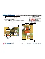
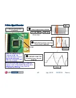
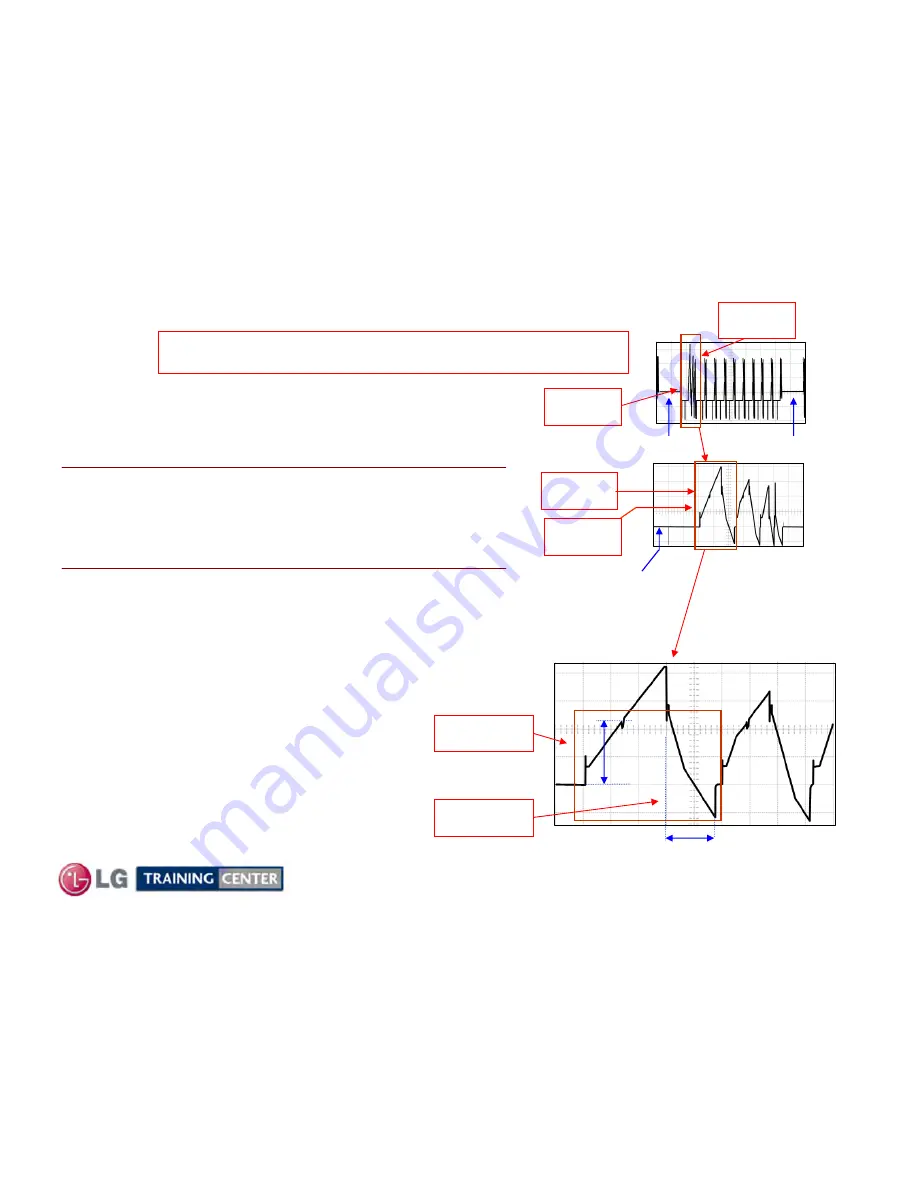
Fig 1:
As an example of how to lock in to the Y-Drive Waveform.
Fig 1 shows the signal locked in at 2ms per/div.
Note the 2 blanking sections.
The area for adjustment is pointed out within the Waveform
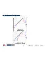
Fig 3:
At 100us per/div the area for adjustment of
SET-UP
or
SET-DN
is now easier to recognize. It is outlined within the Waveform.
Remember, this is the 1
st
large signal to the right of blanking.
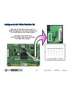
TIP: If you expand to
10
0uSec per/division, the
adjustment for:
SET-UP
can be made using
VR402
and the
SET-DN
can be made using
VR401
.
It will make this adjustment easier if you use the
“Expanded” mode of your scope.
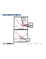
Fig 2:
At 200uSec per/division, the area of the waveform to
use for
SET-UP
or
SET-DN
is now becoming clear.
Now the only two blanking signals are present.
Set must be in “WHITE WASH”
All other DC Voltage adjustments should have already been made.
Area for Set-Up
adjustment
FIG1
2mS
FIG2
200uS
FIG3
100uS
Blanking
Area to
expand
224V
p/p
Expanded from above
Expanded from above
Adjustment
Area
Adjustment
Area
180 uSec
Area for Set-Dn
adjustment
Area to
expand
Blanking
Blanking


