


135
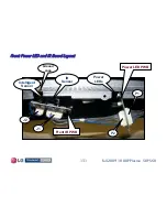
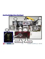
Fall 2009 1080P Plasma 50PS60
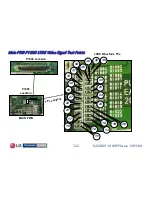
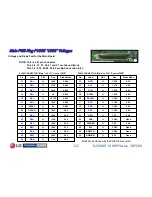
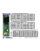
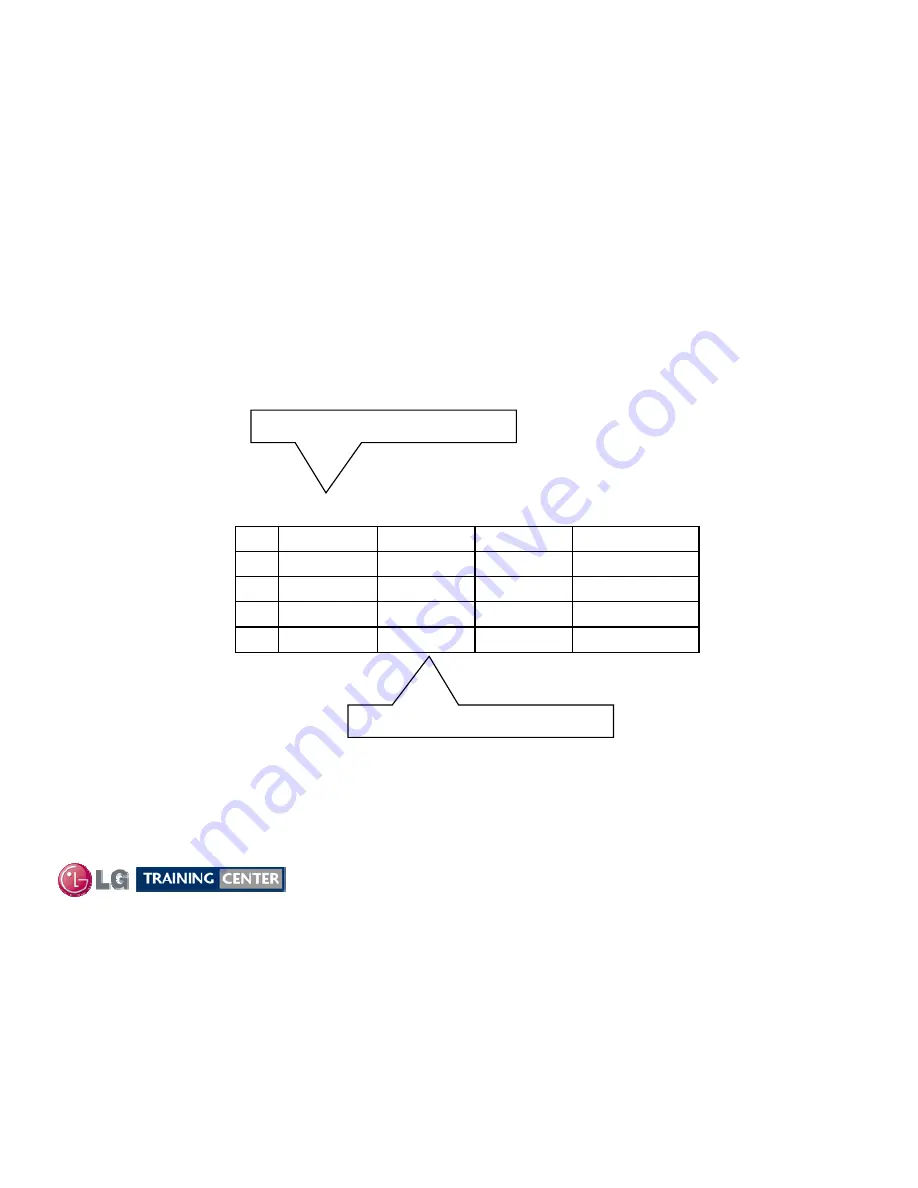
Voltage and Diode Mode Measurements for the Main Board
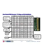
Front IR PWB Plug J2 to Side Key (Voltages and Pin Identificatio
Front IR PWB Plug J2 to Side Key (Voltages and Pin Identificatio
n)
n)
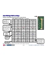
Gnd
Gnd
3.3V
3.3V
*STBY2
Gnd
Gnd
Gnd
4
Open
Gnd
4.38V
3
Open
3.3V
0V
2
Open
3.3V
0V
1
Diode Mode
Run
*STBY1
Pin
J2 CONNECTOR “Ft IR PWB" to "Ft Key“
*STBY2 Power Button “IN”
*STBY1 Power Button “OUT”
Diode Mode Readings taken with all connectors Disconnected. Black lead on Gnd. DVM in Diode Mode.
For Voltages when each Key is pressed, see the Key PWB section.


