


67
Fall 2009 1080P Plasma 50PS60
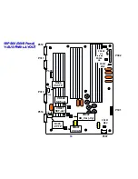
Y DRIVE UPPER AND LOWER PWB SECTION
Y DRIVE UPPER AND LOWER PWB SECTION
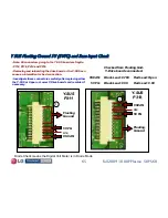
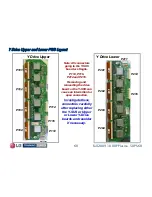
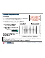
The following section gives detailed information about the
Y Drive boards (Upper and Lower). These boards deliver the
“Y Drive Sustain Signals” to the Panel’s horizontal electrodes,
(This determines the Vertical resolution of the panel).
Each Y Drive board contains 6 buffers (12 total) driving 8 flexible
ribbon cables connecting 1080 horizontal electrodes.
These boards have no DC adjustments.
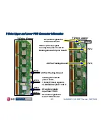
These boards receives their main B+ from the Y
These boards receives their main B+ from the Y
-
-
SUS PWB:
SUS PWB:
•
•
Floating ground 5V from the Switched Mode Power
Floating ground 5V from the Switched Mode Power
Supply on the Y
Supply on the Y
-
-
SUS board.
SUS board.
(Must be measured from the Floating Ground).
(Must be measured from the Floating Ground).
•
•
Y Scan signal (over 500V peak/peak from the Y
Y Scan signal (over 500V peak/peak from the Y
-
-
SUS board).
SUS board).
•
•
Logic signals from the Control board, routed through Y
Logic signals from the Control board, routed through Y
-
-
SUS.
SUS.


