109
August 2009 Plasma 50PS80
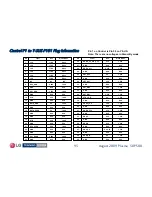
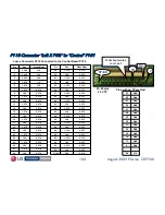
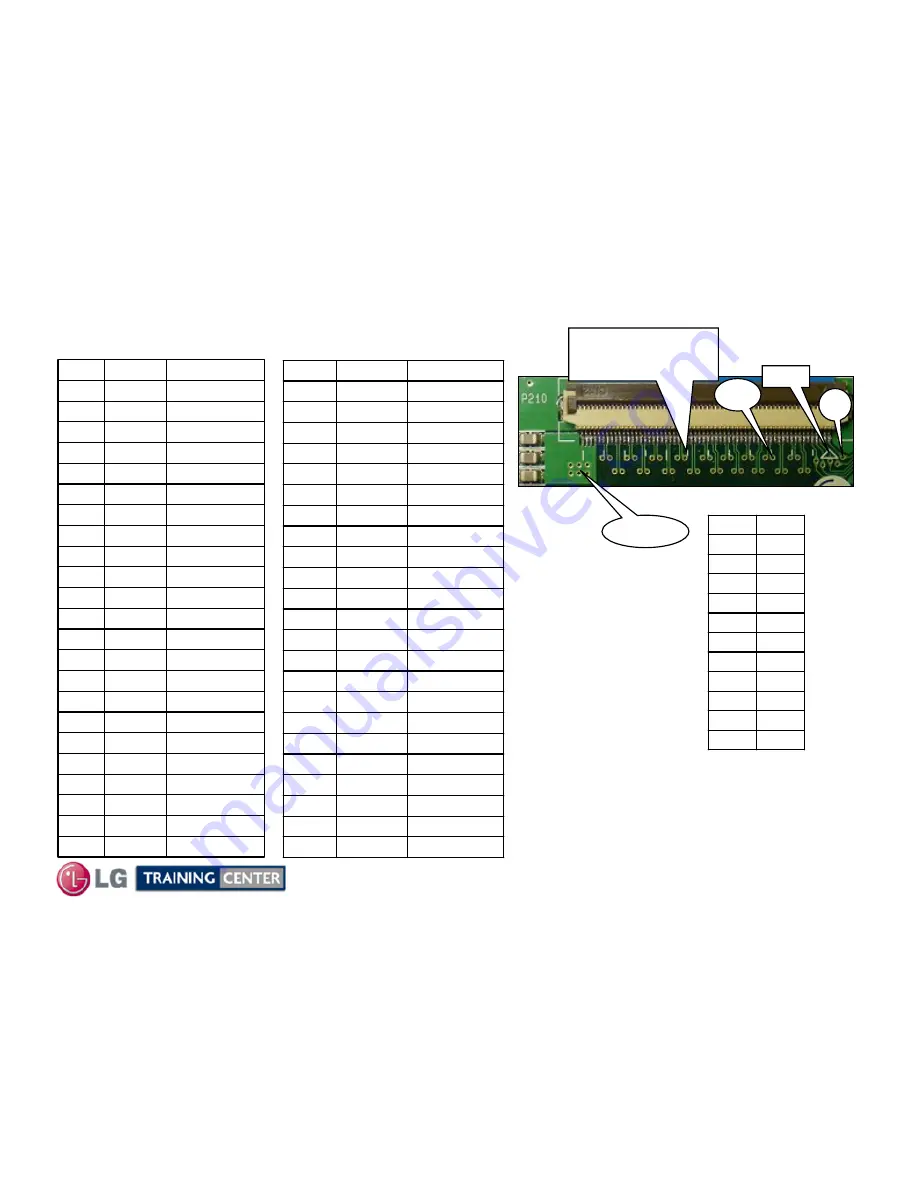
P210 Connector "Center X PWB
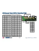
P210 Connector "Center X PWB
“
“
to
to
”
”
Control Board
Control Board
”
”
P102
P102
0.97V
1.0V
28
0.97V
1.27V
27
0.97V
1.0V
25
0.97V
1.27V
24
0.97V
1.0V
22
0.97V
1.27V
21
0.97V
1.0V
20
0.97V
1.27V
19
0.97V
1.0V
17
0.97V
1.27V
16
0.97V
1.0V
15
0.97V
1.27V
14
0.97V
1.0V
12
0.97V
1.27V
11
0.97V
1.0V
10
0.97V
1.27V
9
0.97V
1.0V
8
0.97V
1.27V
7
1.2V
1.87V
5
1.2
1.87V
4
1.2V
3.22V
3
1.1V
0.49V
2
1.1V
0.49V
1
Diode Mode
Run
Pin
Leave Connector P210 Connected to the Control Board P102
0.67V
3.3V
57~60
0.97V
1.0V
55
0.97V
1.27V
54
0.97V
1.0V
53
0.97V
1.27V
52
0.97V
1.0V
50
0.97V
1.27V
49
0.97V
1.0V
48
0.97V
1.27V
47
0.97V
1.0V
46
0.97V
1.27V
45
0.97V
1.0V
43
0.97V
1.27V
42
0.97V
1.0V
41
0.97V
1.27V
40
0.97V
1.0V
38
0.97V
1.27V
37
0.97V
1.0V
35
0.97V
1.27V
34
0.97V
1.0V
33
0.97V
1.27V
32
0.97V
1.0V
30
0.97V
1.27V
29
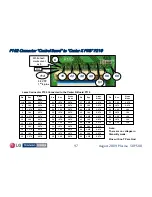
Diode Mode
Run
Pin
Pins with no TP are Gnd.
57~60
57~60
1
1
57~60 pins
3.3V TP
White hash marks
White hash marks
count as 5
count as 5
Pin 1
Pin 1
15
15
n/c
56
Gnd
6
Gnd
13
Gnd
18
Gnd
23
Gnd
26
Gnd
31
Gnd
36
Gnd
39
Gnd
44
Gnd
51

