- 12 -
ADJUSTMENT INSTRUCTIONS
:
EDID DATA for RGB
EDID table =
00 01 02 03 04 05 06 07 08 09 0A 0B 0C 0D 0E 0F
__________________________________________________
00 | 00 FF FF FF FF FF FF 00 1E 6D 01 01 01 01 01 01
10 | 06 0D 01 03 18 5C 34 96 08 CF 72 A3 57 4C B0 23
20 | 09 45 5D EF CE 00 31 D9 31 59 45 59 01 01 01 01
30 | 01 01 01 01 01 40 C3 1E 00 20 41 00 20 30 10 60
40 | 13 00 98 08 32 00 00 18 00 00 00 FC 00 4C 47 20
50 | 54 56 0A 20 20 20 20 20 20 20 00 00 00 FD 00 30
60 | 4C 1E 64 0F 00 0A 20 20 20 20 20 20 00 00 00 00
70 | 00 00 00 00 00 00 00 00 00 00 00 00 00 00 00 C5
8. AD9883A-Set Adjustment
8-1. Synopsis
AD9883A-Set adjustment to set the black level and the Gain
of optimum with an automatic movement from the analog =>
digital converter.
8-2. Test Equipment
Service R/C, 801GF(802B, 802F, 802R) or MSPG925FA
Pattern Generator
(720P The Horizontal 100% Color Bar Pattern output will be
possible and the output level will accurately have to be
adjusted to 0.7±0.1Vp-p)
8-3. Adjustment
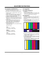
(1) Select Component1 or Component2 as the input with
100% Horizontal Color Bar Pattern(HozTV31Bar) in 720p
Mode and select ‘Normal’ on screen.
(2) After receiving signal for at least 1 second, press the ADJ
Key on the Service R/C to enter the ‘Ez - Adjust’ and select
the ‘3. AD9883A-Set’.
Pressing the Enter Key to adjust with automatic movement.
(3) When the adjustment is over, 'AD9883A Component
Success’ is displayed. If the adjustment has errors,
'AD9883A Configuration Error’ is displayed.
(4) After the Component AD9883A adjustment is over, convert
the RGB-DTV Mode and display Pattern.
When the adjustment is over, 'AD9883A RGB_DTV
Success’ is displayed. If the adjustment has errors,
'AD9883A Configuration Error’ is displayed.
(5) Readjust after confirming the case Pattern or adjustment
condition where the adjustment had errors.
(6) After adjustment is complete, exit the adjustment mode by
pressing the ADJ KEY.
9. Adjustment of White Balance
9-1. Required Equipment
(1) Color analyzer (CA-100 or similar product)
(2) Automatic adjustor (with automatic adjustment hour
necessity and the RS-232C communication being possible)
(3) Pattern Generator(MSPG-925FA): DVI Output
9-2. Connection Diagram of Equipment
for Measuring
(Automatic Adjustment)
[
[
RS-232C Command
(Automatic Adjustment)
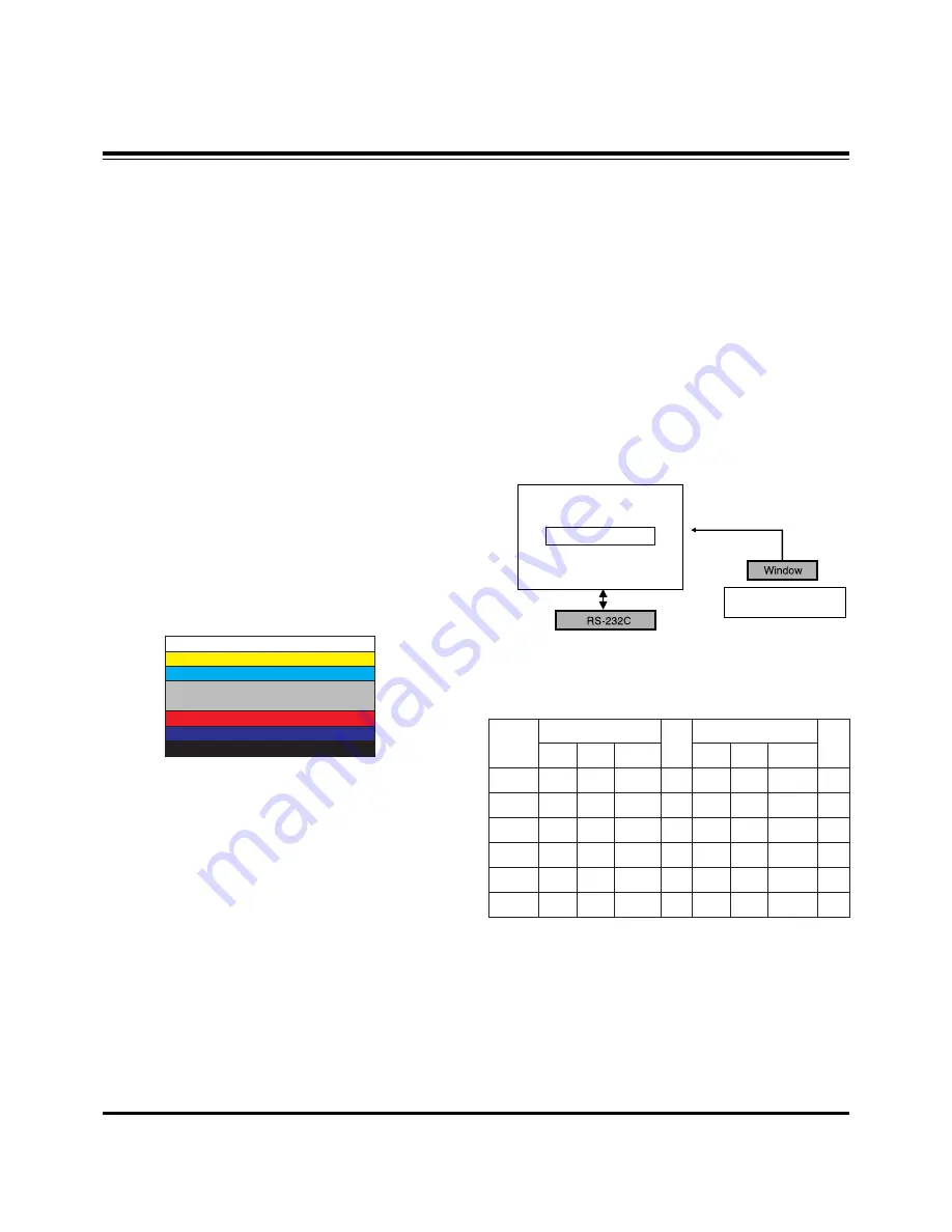
<Fig. 3> Adjustment Pattern : 720P/60Hz HozTV31Bar Pattern
Full White Pattern
Digital RGB
PDP MONITOR
COLOR
ANALYZER
TYPE; CA-100
MSPG-925FA
<Fig. 4> Connection Diagram of Automatic Adjustment
R Gain
G Gain
B Gain
R Cut
G Cut
B Cut
jg
jh
ji
Cool
ja
jb
jc
Med
RS-232C COMMAND
CENTER(DEFAULT)
jd
je
jf
00
00
00
ff
ff
ff
Warm
Min
Max
C0
91
4C
40
40
40
Cool
C0
B3
95
40
40
40
Med
C0
BD
B7
40
40
40
Warm
Summary of Contents for 50PX1D
Page 14: ... 14 BLOCK DIAGRAM ...
Page 15: ... 15 NOTES ...
Page 29: ......
Page 30: ......
Page 31: ......


