


47
Installation
Due to our policy of continuous product innovation, some specifications may change without notification.
©LG Electronics U.S.A., Inc., Englewood Cliffs, NJ. All rights reserved. “LG Life’s Good” is a registered trademark of LG Corp.
fINIsH uP
Accessory Installation
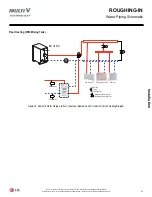
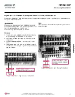
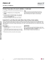
Hydro Kit circuit Water Pump Interlock circuit terminations
1. Verify the pump being installed was sized correctly considering
the system’s design flow rate and static head pressure.
2. If not already completed, install the pump and connect it to the
piping system.
3. Select a suitable pilot ready with a coil rated for 208-230/60/1
service.
4. Connect appropriately sized wiring per local and NEC Code be-
tween the pump starter, the pilot relay, and the Hydro Kit terminal
strip. See Figure 45.
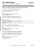
Pump Motor
Starter or
Contactor
Pilot Relay
WIRE TO TERMINALS 1 AND 2
ON HIGH TEMPERATURE (K3) HYDRO KIT
Figure 45: (K3) Hydro Kit -- High Temperature Terminal Block
Total current draw of all connected devices provided by others shall not
exceed 5 Amperes.
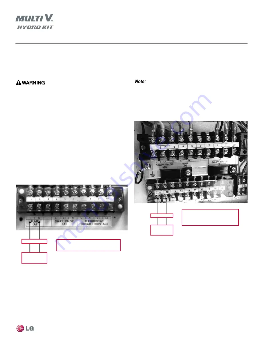
Pump Motor
Starter or
Contactor
Pilot Relay
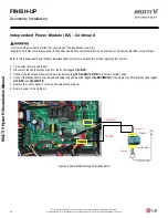
WIRE TO TERMINALS 11 AND 12
ON MEDIUM TEMPERATURE (K2)
HYDRO KIT
Figure 46: (K2) Hydro Kit -- Heating/Cooling Terminal Block
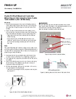
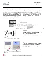
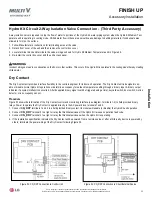
Procedure
Be sure to always have powered off before installation of accessories.
Never operate Hydro Kit outside of the operational parameters as out-
lined in this manual and the product specifications.
Never touch wiring or install accessories with wet hands.
Refer to Figure 45 and Figure 46 for each respective Hydro Kit chassis when following the procedure for Circuit Water Pump Interlock termi-
nation points on the terminal block.


