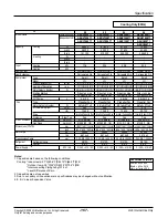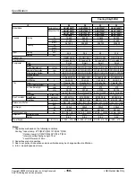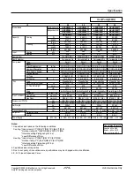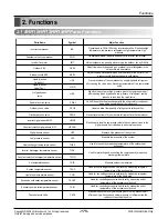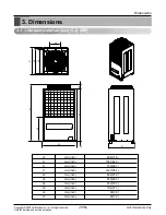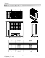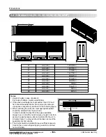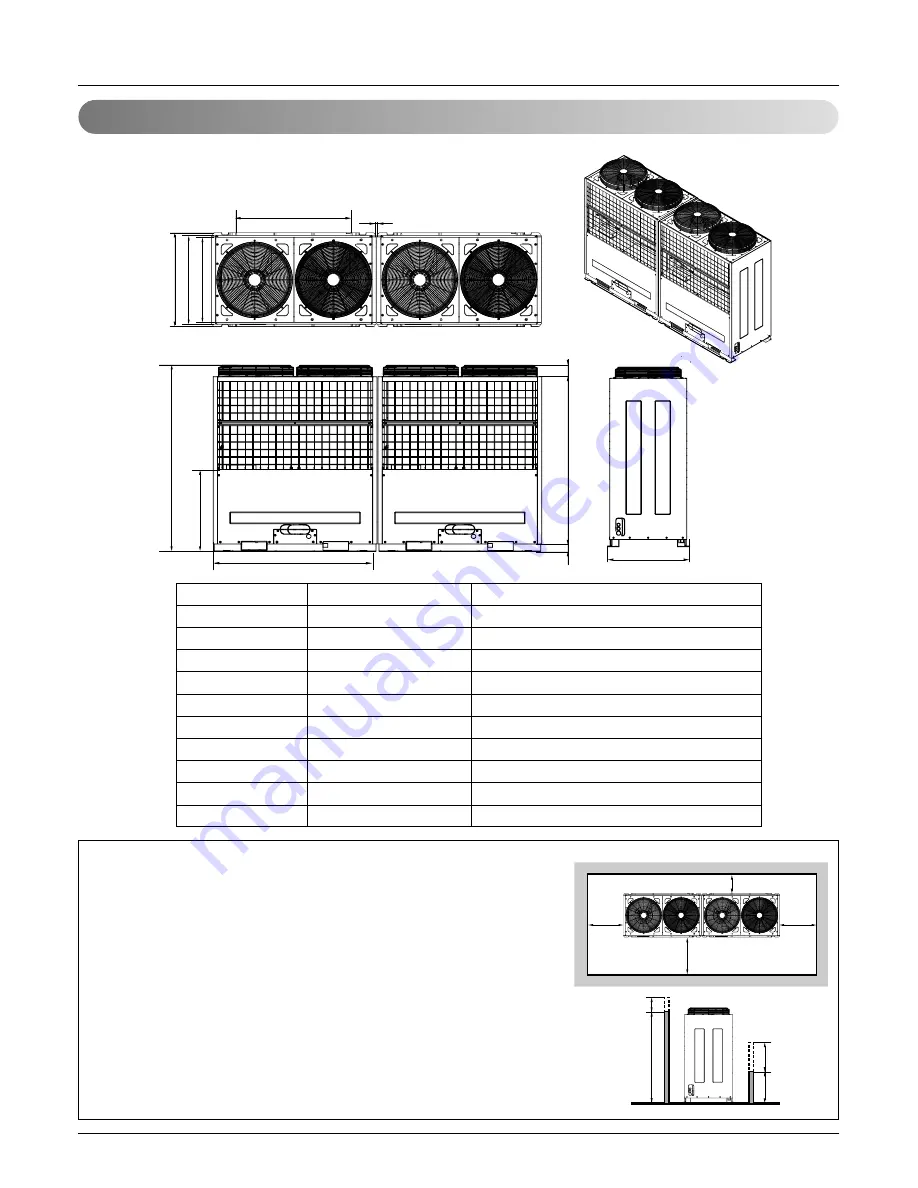
3.3 2 Outdoor Unit (16, 18, 20, 22, 24HP)
Dimensions
L5
H
L6
L1
L7
W
L8
D
L4
L3
L2
D
W
mm(inch)
1280(50.4)
H
mm(inch)
1607(63.3)
D
mm(inch)
730(28.7)
L1
mm(inch)
1427(56.1)
L2
mm(inch)
692(27.2)
L3
mm(inch)
670(26.3)
L4
mm(inch)
900(35.4)
L5
mm(inch)
10(0.4)
L6
mm(inch)
704(27.7)
L7
mm(inch)
99(3.9)
L8
mm(inch)
82(3.2)
Notes:
1. Height of walls in case of pattern1:
Front side:1500mm, Suction side:500mm
2. If the above wall heights are exceeded, then h1/2 and h2/2 should be
added to the front and suction side service spaces respectively as
shown in the following figure.
3. When installing the units, the most appropriate pattern should be
selected from those shown.
In order to obtain the best fit in the space available, always bear in
mind the need to leave enough room for a person to pass between
units and wall and for the air to circulate freely. Your layout should be
taken account the possibility of short circuits.
4. The Units should be installed to leave sufficient space in front for the
on site refrigerant piping work to be carried out comfortably.
1500mm
500mm
h2
h1
F
ront side
Suction side
Front side
250mm or more
900mm or more
250mm
or more
250mm
or more
- 181 -
Copyright ©2009 LG Electronics. Inc. All right reserved.
Only for training and service purposes
LGE Internal Use Only
Summary of Contents for ARNU07GB1G1
Page 338: ...P NO 3828A24006P FEBRUARY 2009 ...

