- 216 -
Copyright ©2009 LG Electronics. Inc. All right reserved.
Only for training and service purposes
LGE Internal Use Only
2) Step 2 : Communication check
- If all model code is displayed in 7 segment including all sub unit,
communication between outdoor units is normal.
- LED5 of sub unit PCB blinks when the sub unit transfers information to the
main unit.
- If LED5 doesn't blink periodically, check communication wires or dip switch
setting.
3) Step 3 : PCB error check
- After 40 sec, error check begins.
■
Main unit
- All errors of units including sub units are displayed in 7 segment.
- If communication with the inverter fan PCB and that with the inverter
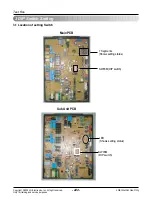
compressor PCB are normal, 2 LED's on the main PCB are blink.
LED01k represents the communication state with the inverter compressor PCB.
LED02k represents the communication state with the inverter fan PCB.
■
Sub unit
- After 40 sec, LED1 blinks once per second.
- If electric phase is reversed or missed, LED6 is on.
- Other LED' except LED1 must be off in initial setup steps.
4) Step 4 : Auto addressing of indoor units
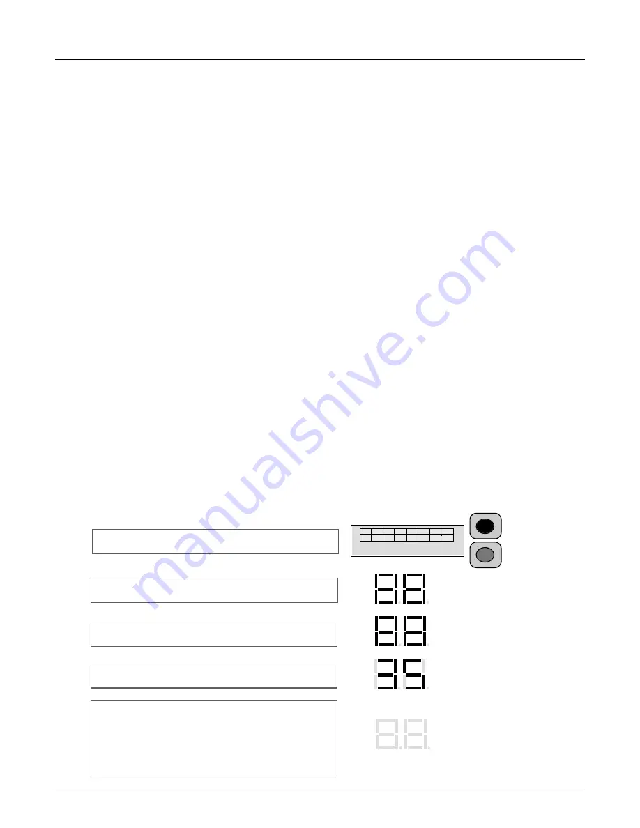
- Auto addressing begins when address(red) button in Main PCB is pressed for 6 sec.
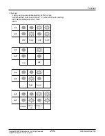
- During auto addressing, 7 segment on main PCB displays "88"
- After auto addressing, the number of indoor units is displayed in 7 segment for 30 sec. The address of each
indoor unit is displayed on each wired remote controller.
Push address(red) button for 6 sec.
Auto address starts
Auto address is in progress (max. 15 min.)
The number of indoor units is displayed for 30 sec.
(35 indoor units found)
Auto address process is finished.
Every indoor unit displays its address on
wired remote controller and the 7 segment of
main PCB is off.
1 2 3 4 5 6 7 8
(6 sec.)
Function
Summary of Contents for ARNU07GB1G1
Page 338: ...P NO 3828A24006P FEBRUARY 2009 ...


