- 232 -
Copyright ©2009 LG Electronics. Inc. All right reserved.
Only for training and service purposes
LGE Internal Use Only
2. Checking Method for Key Components
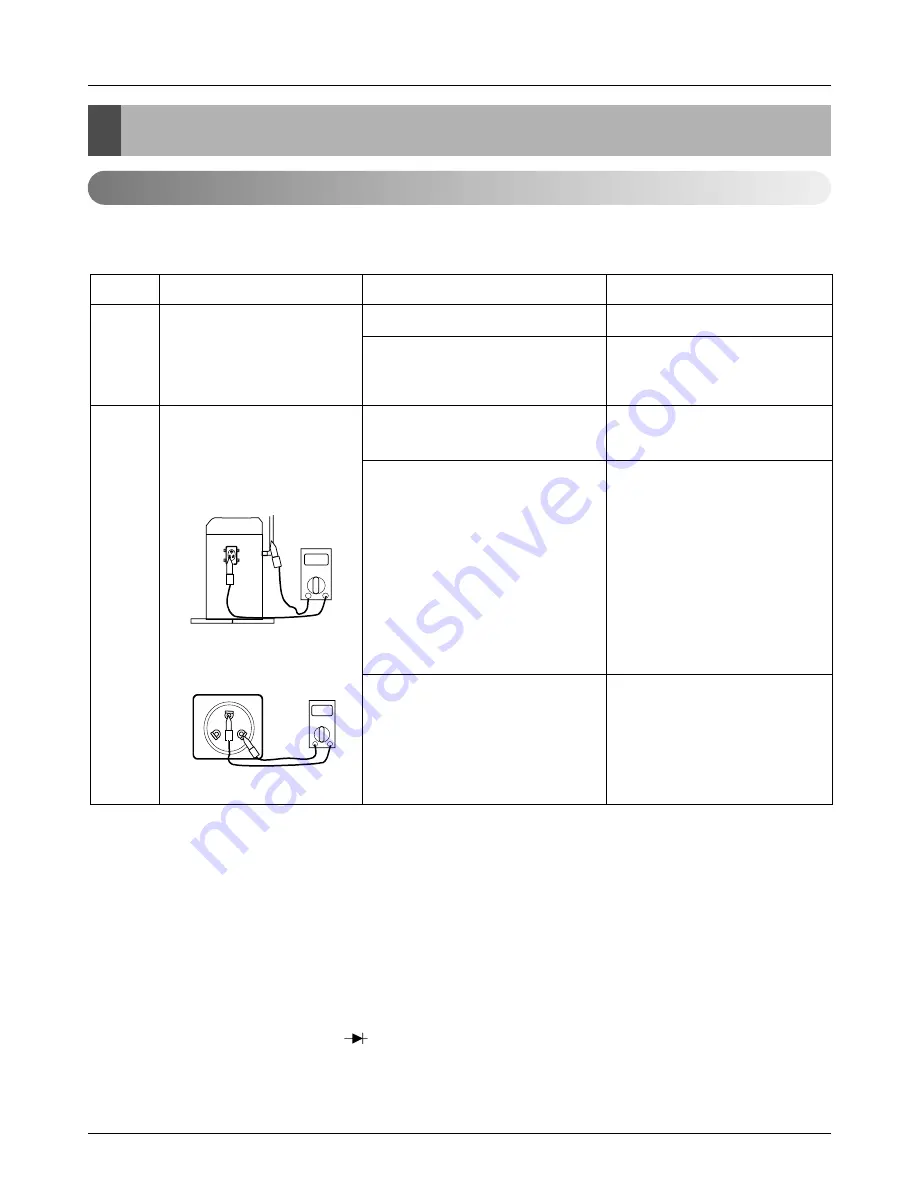
2.1 Compressor
Check and ensure in following order when error related with the compressor or error related with power occurs
during operation:
[Cautions when measuring voltage and current of inverter power circuit]
Measuring values may differ depending on measuring tools and measuring circuits since voltage, current in the
power supply or output side of the inverter has no since waveform.
Especially, output voltage changes when output voltage of the inverter has a pattern of pulse wave.
In addition, measuring values appear largely differently depending on measuring tools.
1) If using a movable tester when checking that output voltage of the inverter is constant (when comparing rela-
tive voltage between lines), always use an analog tester. Especially exercise particular caution if the output
frequency of the inverter is low, when using a movable tester, where change of measured voltage values is
large between other lines, when virtually same values appear actually or where there is danger to determine
that failure of the inverter occurred.
2) You can use rectification voltmeter ( ) if using commercial frequency tester when measuring output values
of the inverter (when measuring absolute values). Accurate measuring values cannot be obtained with a gen-
eral movable tester (For analog and digital mode).
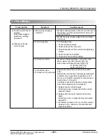
1
2
Is how long power on during
operation?
Does failure appears again
when starting operation?
Method to measure insulation
resistance
Method to measure coil
resistance
1) Power on for 6 hours or more
2) Power on for 6 hours or less
1) The compressor stops andsame
error appears again.
2) If output voltage of the inverter is
stably output. *1
3) If output voltage of the inverter is
unstable or it is 0V.
(When incapable of using a digi-
tal tester)
* Go to No.2.
* Go to No.2 after applying
power for designated time (12
hours).
* Check IPM may fail.
* Check coil resistor and insula-
tion resistor. If normal, restart
the unit. If same symptom
occurs, replace the compres-
sor.
* Insulation resistor: 2MW or
more
Coil resistor: U-V: 1.16±7%
Ω
V-W: 1.19±7%
Ω
W-U: 1.21±7%
Ω
* Check the IPM.
If the IPM is normal, replace
the inverter board.
* Check coil resistor and insula-
tion resistor.
No.
Checking Item
Symptom
Countermeasure
Ω
Comp.
Motor
pipe
Figure 1.
Comp.
Motor
V
U
W
Ω
Figure 2.
Checking Method for Key Components
Summary of Contents for ARNU07GB1G1
Page 338: ...P NO 3828A24006P FEBRUARY 2009 ...


