Troubleshooting Guide
- 289 -
Copyright ©2009 LG Electronics. Inc. All right reserved.
Only for training and service purposes
LGE Internal Use Only
■
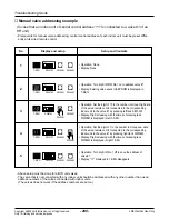
Manual valve addressing flow chart
CAUTION:
If an error is occurred on outdoor unit, man-
ual addressing is not normally completed.
Try manual addressing after checking and
confirming there is no error.
Wait for 3 minute
End of manual addressing
Turn on the power of outdoor unit, HR unit and
indoor unit
Press SW02M of outdoor unit main PCB for 5
seconds
'88' is displayed on outdoor unit main PCB and HR
unit PCB
Enter central control address into each indoor unit
using its wired remote control.
After about 5 minutes, the number of indoor units in
communication are displayed on outdoor unit main
PCB for 30 seconds
On the HR unit PCB, manually set the address of each
valve of an HR unit to the central control address of
indoor unit connected to the valve.
Are the number
of indoor units connected to the outdoor unit
wiring and displayed one(N1)
equal?
Are the number
displayed with H after a while and that of
HR units Installed
equal?
Are all the
blue LED's corresponding to valves
connected to indoor units turned on after
a minute?
Check that No.1 S/W of SW02M on HR unit PCB is
turned on
Immediately turn off the power of outdoor, HR and
indoor units
Check power and communication wiring between
outdoor, HR and indoor units
Retry indoor unit auto-addressing after checking
trouble
Sequence of 2 processes must not change.
Check that the central control address in every
indoor unit and the valve address of every HR unit
are properly inputted
Check that No.2 and 3 of SW02M on HR unit PCB
corresponds to HR unit model
Yes
No
Yes
No
Yes
No
Summary of Contents for ARNU07GB1G1
Page 338: ...P NO 3828A24006P FEBRUARY 2009 ...


