MULTI V
Modular Heat Pump
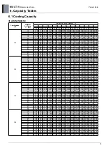
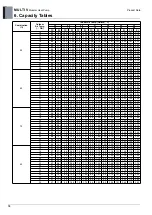
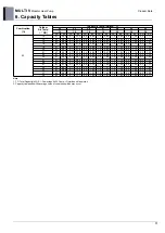
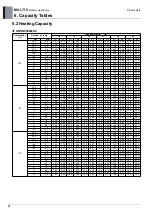
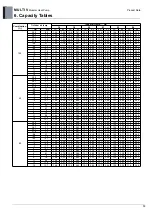
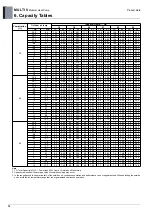
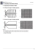
7. Capacity Correction Factor
16
Product Data
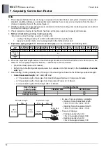
Note
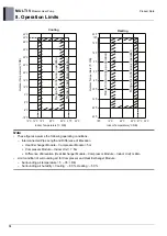
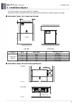
1. These figures illustrate the rate of change in capacity of a standard indoor unit system at maximum load under
standard conditions.(Moreover, under partial load conditions there is only a minor deviation from the rate of
change in capacity shown in the above figures.)
2. With this outside unit, evaporating pressure constant control when cooling, and condensing pressure constant
control when heating is carried out.
3. If heat insulation of piping is insufficient, heat loss will become larger and capacity will decrease.
4.
Method of calculating cooling / heating capacity
:
Maximum cooling / heating capacity of outside units
=
cooling / heating capacity of outside units obtained from capacity table
×
capacity correction factor due to piping length to the farthest indoor unit
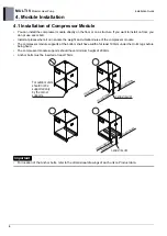
5.
Equivalent piping length for Y Branch and other pipes
can be calculated with following table.
6. When the equivalent length between Heat Exchanger Module and the farthest indoor unit is 90m or more, the
diameter of main pipe(Compressor Module ~ 1st Branch) must be increased.
• (Liquid and Gas pipes are increased.)
• Refer to the table (Refrigerant pipe diameter from outside unit to first branch) in the '
Installation of outside
units
' part.
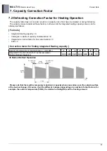
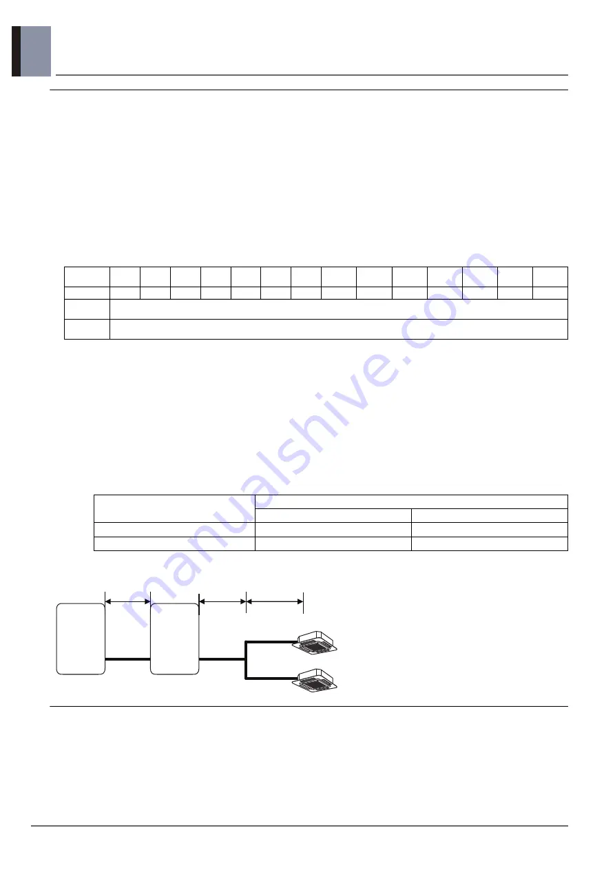
7. Read cooling / heating capacity rate of change in the above figures based on the following equivalent length.
•
Overall equivalent length = L1 + L2 × CF + L3
–
L1 : Equivalent length of main pipe from Heat Exchanger Module to Compressor Module
–
L2 : Equivalent length of main pipe from Compressor Module to 1st Branch
–
L3 : Equivalent length of Branch pipe after 1st Branch
mm
(inch)
Ø6.35
(1/4)
Ø9.52
(3/8)
Ø12.7
(1/2)
Ø15.8
8 (5/8)
Ø19.0
5 (3/4)
Ø22.2
(7/8)
Ø25.4
(1)
Ø28.58
(1-1/8)
Ø31.8
(1-1/4)
Ø34.9
(1-3/8)
Ø38.1
(1-1/2)
Ø41.3
(1-5/8)
Ø44.5
(1-3/4)
Ø53.98
(2-1/8)
Elbow (m)
0.16
0.18
0.2
0.25
0.35
0.4
0.45
0.5
0.55
0.6
0.65
0.7
0.75
0.85
Y Branch
(m)
0.5
Header
(m)
1
Rate of change
(object piping)
Correction factor
standard size
size increase
Cooling(Gas pipe)
1
0.5
Heating(Liquid pipe)
1
0.2
• In case of increased piping installation
– (Cooling) Overall equivalent length
= 30 m + 30 × 0.5 + 40 m = 85 m
– (Heating) Overall equivalent length
= 30 m + 30 × 0.2 + 40 m = 76 m
• The rate of change
– Cooling capacity when HU
= 0m is thus approximately 0.89
– Heating capacity when HU
= 0m is thus approximately 1.00
Comp.
Module
30m
30m
Equivalent length
40m
Branch
Indoor Unit
Indoor Unit
Gas pipe
Liquid pipe
HEX
Module
Equivalent length
Summary of Contents for ARUN050GME0
Page 1: ...Modular Heat Pump R410A 50Hz 5CVD0 01A P No MFL67474053 ...
Page 2: ...MULTI V S Modular Heat Pump General information Product Data Installation Guide ...
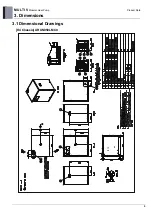
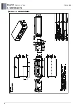
Page 11: ...MULTI V Modular Heat Pump 3 Dimensions 6 Product Data GG B8 Chassis ARUN050GME0 ...
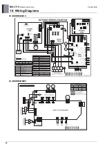
Page 27: ...22 MULTI V Modular Heat Pump Product Data 10 Wiring Diagrams ARUN050LMC0 ARUN050GME0 ...


