


Ceiling Concealed Duct
Inverter
50Hz/R410A
_
21
Part 2 Product Data
5. Refrigerant Cycle Diagrams
Models
Pipe Size
Length A(m)
Elevation B(m)
*Additional
refrigerant(g/m)
(Diameter:Ø mm)
Gas
Liquid
Standard
Max.
Standard
Max.
B30AWYN7G5A
15.88
9.52
7.5
50
5
30
40
B30AWYU4G5A
B36AWYN7G5A
15.88
9.52
7.5
50
5
30
40
B36AWYU4G5A
B42AWYN7G5A
15.88
9.52
7.5
50
5
30
40
B42AWYU4G5A
B55AWYN7G5A
15.88
9.52
7.5
50
5
30
40
B55AWYU3G5A
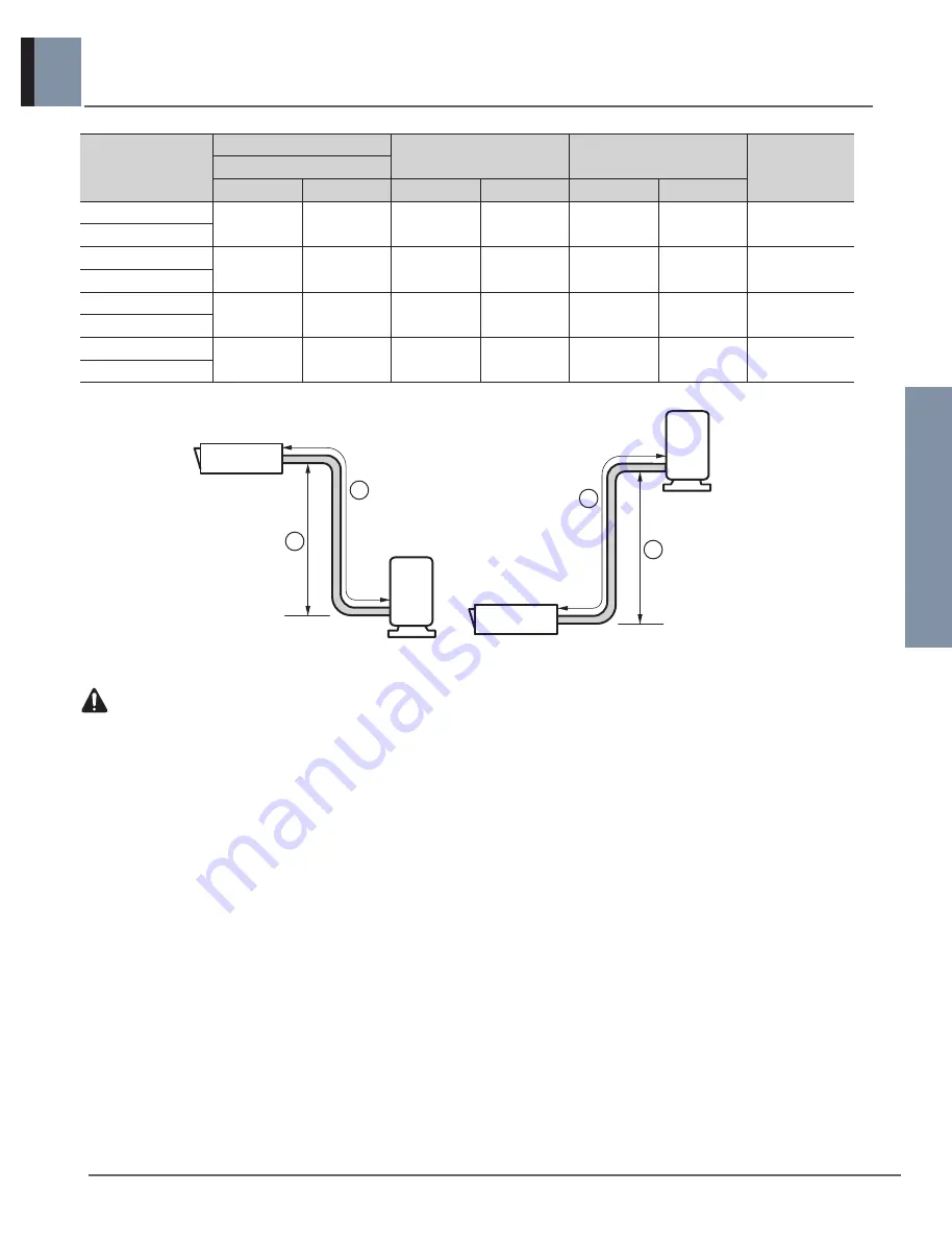
Outdoor unit
Indoor unit
A
B
Outdoor unit
Indoor unit
A
B
CAUTION
• If installed tube is shorter than 20 m, additional charging is not necessary.
The pipe length exceeds 20m, it need to additionally charge refrigerant which according to the table.
• If 55 kBtu/h Model is installed at a distance of 50m, 1,200g of refrigerant should be added.
(50-20) × 40 =1,200g
• Capacity is based on standard length and maximum allowance length is on the basis of reliability.
• Improper refrigerant charge may result in abnormal cycle.
• Oil trap is not required.


