


3. Signal detection of the P/U
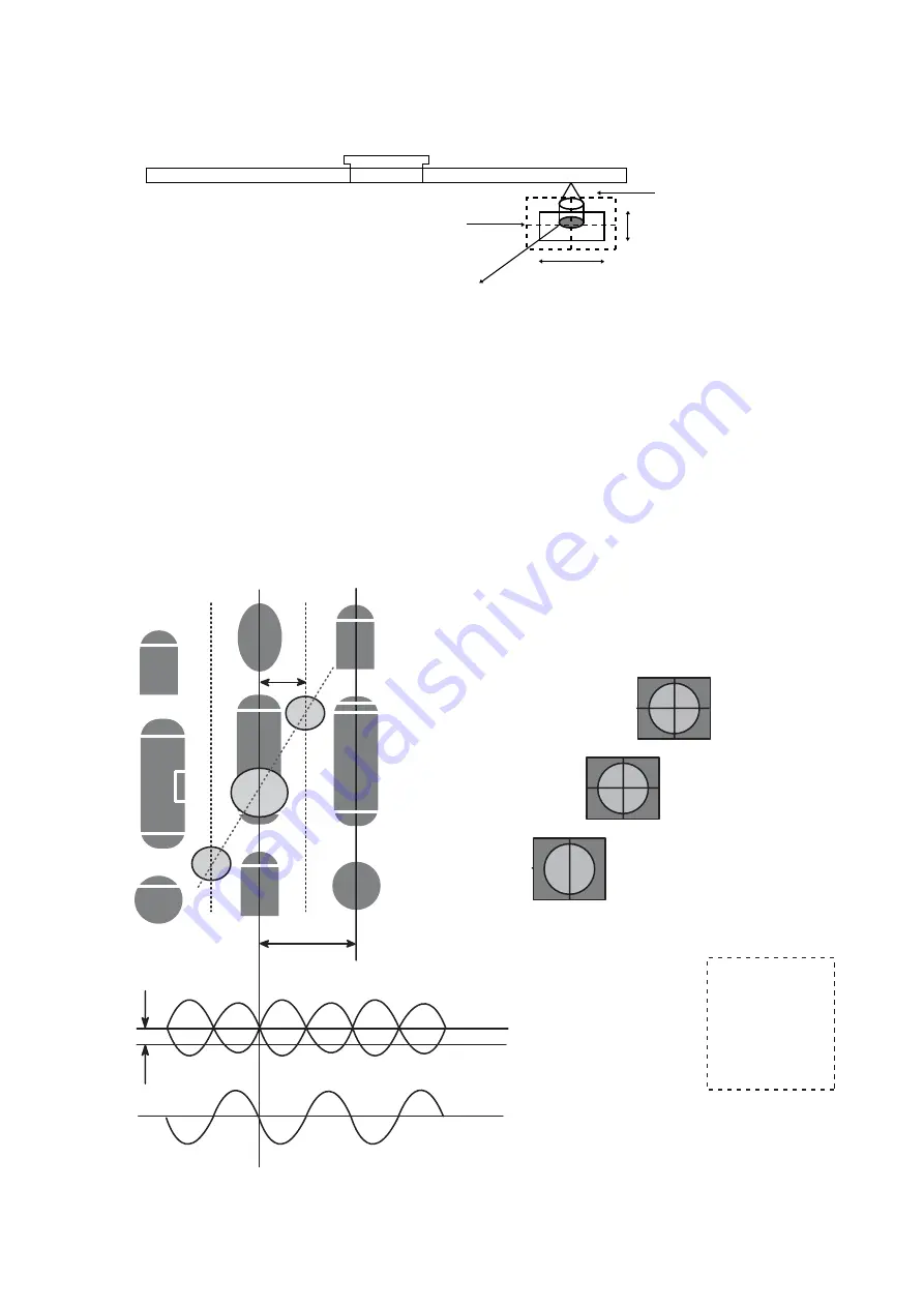
1) Focus Error Signal ==> (A+C)-(B+D)
This signal is generated in DSP IC(IC101 : MT1959H) controls the pick-up's up and down to focus on
Disc.
2) Tracking Error Signal (DPP Method) ==> {(A+D)-(B+C)}- k x {(EF
1
+EF
4
)-(EF
2
+EF
3
)}
This signal is generated in DSP IC(IC101 : MT1959H) controls the pick-up's left and right shift to find to
track on Disc.
3) RF Signal ==> (A+B+C+D)
This signal is converted to DATA signal in DSP IC(IC101 : MT1959H)
25
Pick-Up module
Photo Diode
Tracking
Focusing
Infrared Iaser
k
[(EF1+EF4) - (EF2+EF3)]
(A+D) - (B+C)
(A+D) - (B+C) -
k
[(EF1+EF4) - (EF2+EF3)]
Offset
TE
Tp
Sub2
Main
Tp/2
Sub1
Track Center
E4, E3
E1, E2
D, C
A, B
F4, F3
F1, F2
EF1=E1+F1
EF2=E2+F2
EF3=E3+F3
EF4=E4+F4
Summary of Contents for BP50NB40
Page 17: ...17 A B C 1 2 3 4 5 A00 A01 002 003 461 005 001 463 006 462 004 PBM01 B B EXPLODED VIEW ...
Page 23: ...23 2 CONNECTOR 66 PIN ASSIGNMENT ...
Page 24: ...24 ...
Page 29: ...29 3 1 2 Block Diagram Seek IC101 MT1959H ...
Page 34: ...1 2 Pin Layout RF Part 34 ...
Page 35: ...35 ...
Page 36: ...36 ...
Page 37: ...37 ENDEC Part ...
Page 38: ...38 ...
Page 39: ...39 ...
Page 40: ...40 ...
Page 41: ...41 ...
Page 42: ...42 ...
Page 43: ...43 ...
Page 44: ...44 ...
Page 45: ...45 IC601 TPIC2016G SPINDLE MOTOR AND 10CH ACTUATOR DRIVER Terminal Assignments ...


