


27
2. Focus Circuit
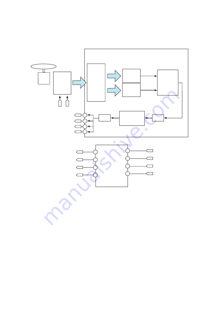
2-1. Block Diagram
Disc
Motor
Unit
Optical
Pick-up
HOP-
B7710G
A ~H
FACT-
FACT+
SIMO
DAC
Focusing
Compensator
ADC
FE
Offset
Calibration
&
Signal
Calculation
VAR_INA ~
VAR_IND
VAR_INE ~
VAR_INH
IC101
MT1959H
MFEO
VAR_MFEO
VAR_SFEO
Generation
Generation
SFEO
Generation
FE
39
SOMI
41
SCLK
42
SSZ
91
FCS2+
39
FCS2_
41
FCS1+
42
FCS1-
SSZ
SCLK
SIMO
SOMI
91
10
11
12
13
IC601
TPIC2010G4
2-2. Focus Servo
The aim of Focus Servo is to maintain the distance between object lens of P/U and disc surface, so that the
detected RF signal(A, B, C, D, EF1, EF2, EF3, EF4) can be maximized.
Focus Error Signal(FE) generates from focus error detection block in DSP IC(MT1959) using Conventional
Astigmatism Detection method, Differential Astigmatism Detection method.
Focus Gain and path can be changed at the DSP IC according to the disc.
The Focus Search operation is using FE, PE Signal, therefore check FE, PE signals when Focusing is failed.
The role of DSP IC(MT1959) is Focus Digital Controller. The operation path is as follows;
FE Signal is input to DSP IC, and after A/D Conversion, Digital Equalizer Block and D/A Conversion in MT1959,
the output signal SSZ, SCLK, SIMO, SOMI(MT1959H 90, 42, 39, 41) is input to Drive IC(TPIC2010G4)
The drive output signal FCS2+/FCS2-/FCS1+/FCS1- generated according SSZ, SCLK, SIMO,
SOMI(TPIC2010G 4 10-13pin), and drives focus actuator in the P/U unit.
Summary of Contents for BP50NB40
Page 17: ...17 A B C 1 2 3 4 5 A00 A01 002 003 461 005 001 463 006 462 004 PBM01 B B EXPLODED VIEW ...
Page 23: ...23 2 CONNECTOR 66 PIN ASSIGNMENT ...
Page 24: ...24 ...
Page 29: ...29 3 1 2 Block Diagram Seek IC101 MT1959H ...
Page 34: ...1 2 Pin Layout RF Part 34 ...
Page 35: ...35 ...
Page 36: ...36 ...
Page 37: ...37 ENDEC Part ...
Page 38: ...38 ...
Page 39: ...39 ...
Page 40: ...40 ...
Page 41: ...41 ...
Page 42: ...42 ...
Page 43: ...43 ...
Page 44: ...44 ...
Page 45: ...45 IC601 TPIC2016G SPINDLE MOTOR AND 10CH ACTUATOR DRIVER Terminal Assignments ...


