4
LOCATION OF CUSTOMER CONTROLS
(1)
Headphone Jack
3.5mm jack for monitoring the audio signal from audio
CDs.
(2)
Headphone Volume Control
Adjusts the headphone sound level.
(3)
Disc Drawer
Accepts a CD-ROM disc on its tray.
(4)
Busy Indicator
The Busy Indicator lights during initialization and data-
read operations.
(5)
Emergency Eject Hole
Insert a paper clip here to eject the drawer manually or
when there is no power.
(6)
Play/Skip Button
When an Audio CD is in the Disc Drawer, pressing
this button will start playing audio CDs from the first
track. If an audio CD is playing, pressing this button
will skip to the next track.
(7)
Open/Close/Stop Button
This button is pressed to open or close the CD tray.
If an audio CD is playing, pressing this button will stop
it, and pressing it
again will open the tray.
COMPACT
1
2
5
4
6
7
3
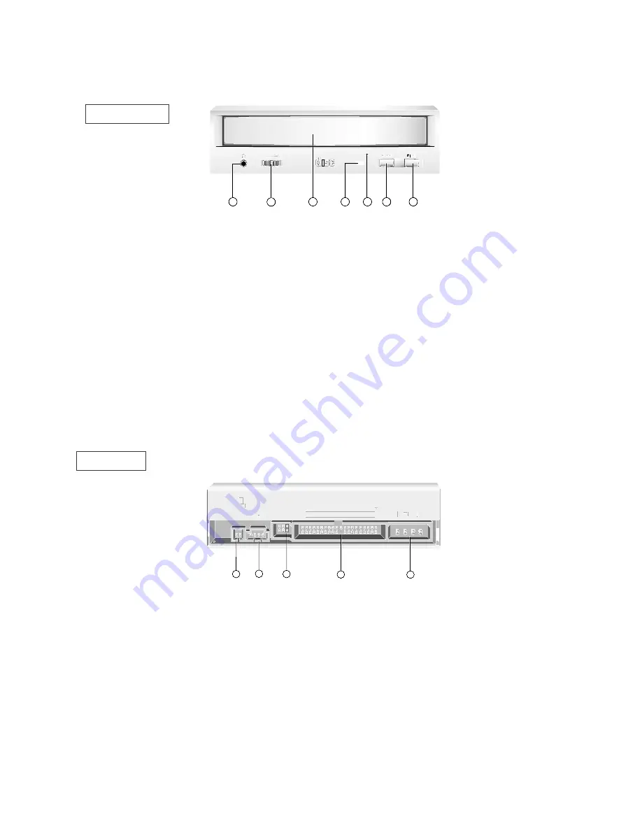
Figure 1. Front View
(1)
Digital Audio Output Connector
This is a digital audio output connector or Video CD
output connector.
You can connect this to the digital audio system or
Video CD Board.
(2)
Analog Audio Output Connector
The Audio Output Connector connects to a sound
card.
The supplied audio cable is a SoundBlaster
®
type
cable. If you have a different sound card, you will
need to contact the sound card manufacturer to obtain
the proper cable for that card.
(3)
Master / Slave / CSEL Jumper
These three jumpers are used to set the CD-ROM
Drive to either a Master, Slave, or CSEL drive.
(4)
Interface Connector
This 40-pin connector is used to transfer and control
signals between the CD-ROM Drive and your PC.
Connect the 40-pin IDE cable in your PC to this
connector.
(5)
Power-in Connector
Attach a power cable from the computer to this
connector.
Figure 2. Back View
DIGITAL
ANALOG
INTERFACE
POWER
D
R
C S M
S L A
G L
G
39
1
+5
+12
GND
40
2
AUDIO
AUDIO
1
2
5
4
3
FRONT
REAR
Figure 2. Back View


