background image

Website:http://www.LGservice.com [For U.S.A]
www.lg.ca [For Canada]

ELECTRIC & GAS DRYER

SERVICE MANUAL

CAUTION    

READ THIS MANUAL CAREFULLY TO DIAGNOSE 
TROUBLES CORRECTLY BEFORE  OFFERING SERVICE.

MODEL : 

DLE5977W/DLG5988W
DLE5977B/DLG5988B
DLE3777W/DLG3788W

Summary of Contents for D5988B

Page 1: ...vice com For U S A www lg ca For Canada ELECTRIC GAS DRYER SERVICE MANUAL CAUTION READ THIS MANUAL CAREFULLY TO DIAGNOSE TROUBLES CORRECTLY BEFORE OFFERING SERVICE MODEL DLE5977W DLG5988W DLE5977B DLG5988B DLE3777W DLG3788W ...

Page 2: ...Feb 2004 PRINTED IN KOREA P No 3828EL3005A ...

Page 3: ...ms are present everywhere ESD may damage or weaken the electronic control assembly The new control assembly may appear to work well after repair is finished but failure may occur at a later date due to ESD stress Use an anti static wrist strap Connect wrist strap to green ground connection point or unpainted metal in the appliance OR Touch your finger repeatedly to a green ground connection point ...

Page 4: ...TOR TEST MEASURE WITH POWER OFF 21 9 3 TEST 3 MOTOR TEST 22 9 4 TEST 4 MOISTURE SENSOR 23 9 5 TEST 5 DOOR SWITCH TEST 24 9 6 TEST 6 HEATER SWITCH TEST ELECTRIC TYPE 25 9 7 TEST 7 GAS VALVE TEST GAS TYPE 26 10 CHANGE GAS SETTING NATURAL GAS PROPANE GAS 27 11 DISASSEMBLY INSTRUCTIONS 29 12 EXPLODED VIEW 36 12 1 CONTROL PANEL PLATE ASSEMBLY 36 12 2 CABINET DOOR ASSEMBLY 37 12 3 1 DRUM MOTOR ASSEMBLY ...

Page 5: ...ronic 15W 125mA GAS VALVE 13W 110mA X 2 5400W 22 5A 5 5 250W 4 5A ELECTRICITY CONSUMPTION Blue White Black Material Finishes DLE3777W DLE5977W DLG3788W DLG5988W DLE5977B DLG5988B ITEM Child Lock Reversible Door Interior Light Product WXHXD Packing WXHXD Audible End of Cycle Beeper Dryer Rack Drum No of Dry Levels No of Dry Option No of Programs DRUM CAPACITY CONTROL TYPE No of Temperature Controls...

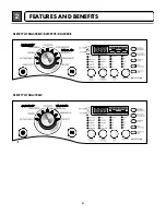
Page 6: ...5 FEATURES AND BENEFITS 2 DLE5977W DLG5988W DLE5977B DLG5988B DLE3777W DLG3788W ...

Page 7: ...er the screw of the terminal block hooked end facing rightward and pinch the hook together and screw tightly 4 wire connection Direct wire Use the instructions at this section if your home has a 4 wire receptacle NEMA type 14 30R and you will be using a UL listed 120 240 volt minimum 30 amp dryer power supply cord 4 wire receptacle NEMA type14 30R 5 12 7 cm 31 2 8 6 cm 1 2 5 cm 5 12 7 cm 1 2 5 cm ...

Page 8: ...und wire at 5 in 12 7cm Cut 11 2 in 3 8cm from 3 remaining wires Strip insulation back 1in 2 5cm Shape ends of wires into a hook shape 1 Take off center terminal block screw 2 Put the hooked end of the neutral wire white of power supply cable under the center screw of terminal block Squeeze the hooked end together 3 Connect the hooked ends of the other power supply cable to the center screw of ter...

Page 9: ...er supply cord to the center silver colored terminal screw of the terminal block Tighten screw 3 Connect the other wires to outer terminal block screws Tighten screws 4 Tighten strain relief screws 5 Insert tab of terminal block cover into slot of dryer rear panel Secure cover with hold down screw e a d b c d g f a lf your local codes or ordinances permit the connection of a frame grounding conduc...

Page 10: ...xternal ground conductor screw Tighten screw 4 Connect neutral wire white or center wire of power supply cord to the center silver colored terminal screw of the terminal block a b c a External ground connector b Green or bare copper wire of power supply cord c 3 4 in 1 9 cm UL listed strain relief d Center silver colored terminal block screw e Neutral grounding wire white f Neutral wire white 5 Co...

Page 11: ...cable under center silver colored terminal block screw Tighten screw 3 Connect the other wires to outer terminal block screws Tighten screws 4 Tighten strain relief screws 5 Insert tab of terminal block cover into slot of dryer rear panel Secure cover with hold down screw 6 Connect a separate copper ground wire from the external ground connector screw to an adequate ground Option 3 Optional 3 wire...

Page 12: ...tor 4 Tighten all connections securely Turn on gas and check all pipe connections internal external for gas leaks with a non corrosive leak detection fluid 5 For L P Liquefied Petroleum gas connection refer to section on Gas Requirements For further assistance refer to section on Gas Requirements 1 New Stainless Steel Flexible Connector Use only if allowed by local codes Use Design A G A Certified...

Page 13: ...ation Saturation 55min 41min 36min 32min 34min 25min 20min 30min 5min 5min 5min 5min 5min 5min 5min 5min N A 68 4 C 66 4 C 60 4 C 52 3 C 52 3 C 45 3 C 70 5 C 66 5 C No heater 47 5 C 47 5 C 47 5 C 47 5 C 38 5 C 38 5 C 47 5 C 47 5 C N A Saturation Load Sensor Dry Manual Dry Default Drying Electro sensor Temp Control Default time Temp Control Cooling Wrinkle care Conditions of operation and terminati...

Page 14: ... Heater case Hi limit Electric type 3 Outlet Thermostat Auto reset Check Top Marking N85 Measure resistance of terminal to terminal Open at 185 9 F 85 5 C Close at 149 9 F 65 5 C Same shape as Thermal cut off Resistance value Resistance value 5Ω Blow housing Safety Electric type 4 Lamp holder Measure resistance of terminal to terminal Resistance value 80Ω 100Ω 6 Idler switch Measure resistance of ...

Page 15: ... 58 F 10 40 C 58 F 104F 10 40 C Resistance value 10Ω Heater case Hi limit Electric type 9 Motor See Page 13 10 Gas valve valve 1 valve 2 Measure resistance of the following terminal Valve 1 terminal Valve 2 terminal Resistance value 1 5kg Resistance value 1 5 2 5kg Gas type 11 Igniter Measure resistance of terminal to terminal Resistance value 100 800Ω Gas type 12 Frame Detect Measure resistance o...

Page 16: ... terminal Open at 203 7 F 95 5 C Close at 158 9 F 70 5 C Resistance value Continuity 1Ω Gas type Gas funnel 13 Outlet Thermostat Manual reset Check Top Marking N100 Measure resistance of terminal to terminal Open at 212 12 F 100 7 C Manual reset If thermal fuse is open must be replaced Resistance value Continuity 1Ω Gas type Gas funnel ...

Page 17: ... On Off by Centrifugal Switch STOP MODE When Motor does not operate RUN MODE Motor operates When checking Component be sure to turn Power off then do voltage discharge sufficiently NOTE Centrifugal switch Centrifugal switch Pull Drive forward ...

Page 18: ...LAY OUT MODEL DISPLAY AS DIAGNOSTIC TEST MODEL DLE5977W B DLG5988W B DLE3777W DLG3788W OP 1 X X X X OP 2 X X X X OP 3 X O X O OP 4 O O X X OP 5 X X X X OP 6 X X X X 6871EC1115A 6871EC1115B 6871EC1115C 6871EC1115D 18 FO 19 FO 18 F1 19 F1 OPTION PART LED DISPLAY P No ...

Page 19: ...18 ELECTRIC DRYER WIRING DIAGRAM WIRING DIAGRAM 8 GAS DRYER WIRING DIAGRAM ...

Page 20: ... pressing start 1 time step 2 by pressing start 2 times step 3 by pressing start 3 times and step 4 by pressing start 4 times in sequence Press Start 2 times and then open the door Proceed again from the step 1 all the way to the step 4 Press Start 3 times and then open the door Proceed with the step 1 and skip the step 2 and press step 3 twice and finish with step 4 by making sure the all the ele...

Page 21: ...et is the voltage 110V 125V AC YES NO Check the fuse or circuit breaker Check if the voltage measured between Connector RD3 Black linked to the Controller and WH3 White is 110V 125V YES NO Check if Power Cord is properly connected Reconnect the controller Replace controIler Check if the Controller wire is disconnected Check if Terminal Block and Power Cord are connected Check Plug Does Power Cord ...

Page 22: ... 1 when measuring 6pin connector Pin Blue wire and Pin Red wire connected to Controller NO YES Check if Control and 6Pin connector is properly connected Replace Controller Check Harness linking connector Take 6pin Connector from the Controller Table 1 Resistance for Thermistor Temperature Check if resistance is in the range of Table 1 when measuring resistance between terminals after separating Ha...

Page 23: ... from Motor Pulley Is resistance below 3Ω between Connector WH3 White wire and BL2 Yellow wire Measure while door is closed YES NO Check if Door flame presses door switch knob Check Door Switch Check Harness connection Is resistance below 3Ω between Connector BL2 Yellow wire and BL2 Brown wire NO YES Replace Control Relay check Check Controller connector Is resistance below 1Ω between terminals of...

Page 24: ...5V 2 0V 4 0V Over 4 0V Weight after removing from Washing Machine Damp Dry Completely dried clothes Display Value Voltage DC between 6Pin terminal Remark Short with metal to 6pin connector s Pin BLUE wire and Pin ORANGE wire to Controller When measuring resistance in Electric load is resistance below 1Ω YES NO When contacting cloth to Electro load 1 Is the measurement within the range of Table 2 d...

Page 25: ...d RD3 Black wire Connector WH3 RD3 after taking WH3 RD3 out from Controller NO YES Door switch Check Refer to Component testing Measure while Door is open Check if resistance is 300 60Ω between WH3 White wire and RD3 Black wire Connector WH3 RD3 after taking WH3 RD3 out from Controller YES NO Check Lamp When opening Lamp replace then measure again Door switch Check Refer to Component testing Measu...

Page 26: ...heck Motor Check if the value of measured resistance is below 1Ω between terminal and at RUN condition YES NO Check Motor and replace it 1 Is resistance between Heater terminal and below 18 22Ω 2 Is resistance between Heater terminal and below 18 22Ω 3 Is resistance between Heater terminal and below 9 11Ω YES NO Replace Heater Check if the value of measured resistance is below 1Ω between terminal ...

Page 27: ... When measuring terminal resistance on Valve 1 Valve 2 Value is more than1 5 2 5kΩ Measure after Off NO YES Change Valve Check thermostat Hi limit Safety Igniter operates after 1 min Igniter becomes reddish YES NO Check Igniter Frame detect When measuring Valve 2 voltage Value is more than AC 90V 10 sec after Igniter off NO YES Check Gas connection or Gas supply When measuring Valve 1 voltage More...

Page 28: ... to authorized servicers only CHANGE GAS SETTING NATURAL GAS PROPANE GAS 10 Warning STEP 1 VALVE SETTING Full open Change screw STEP 2 ORIFICE CHANGE Orifice Gas type Natural Gas Propane Gas Marking NCU PCU Shape Orifice P No 4948EL4001B 4948EL4002B Close Change screw Remove 2 screws Disassemble the pipe assembly Replace Natural Gas orifice with Propane Gas orifice Kit contents Orifice Dia 1 613mm...

Page 29: ...CLOSE VALVE 1 IGNITER VALVE 2 FRAME DETECT OPEN GAS VALVE STRUCTURE GAS VALVE FLOW START KEY PUSH DRYING VALVE 1 ON VALVE 2 ON IGNITE ON FRAME DETECT OPEN IGNITE OFF IGNITE TEMPERATURE ABOUT 370 F GAS IGNITION FRAME DETECT CLOSE VALVE 2 OFF NO NO YES YES ...

Page 30: ...29 Disassemble and repair the unit only after pulling out power plug from the outlet DISASSEMBLY INSTRUCTIONS 11 1 Remove 3 screws on the plate upper 2 Push the top plate 3 Open the top plate ...

Page 31: ... the control panel frame 2 Disconnect the connectors 3 Pull the control panel assembly 4 Remove 9 screws on the PWB PCB assembly display 5 Remove 4 screws on the PWB PCB assembly main 6 Disassemble the control panel assembly ...

Page 32: ...31 1 Open the top plate 2 Open the control panel assembly 3 Open the door assembly 4 Remove 2 screws 5 Remove 4 screws from upper side 6 Disconnect the harness of door switch ...

Page 33: ...plate 2 Remove the Cover Cabinet and Tub drum front 3 Disengage belt from motor and idler pulleys 4 Carefully remove Drum out through front of dryer 1 2 1 1 Open the door 2 Remove the screw holding the drum lamp shield in place 3 Slide the shield up and remove 4 Remove the bulb and replace with a 15 watt 120 volt candelabra base bulb 5 Replace the lamp shield and screw ...

Page 34: ...n 28cm to the blower housing and attach the duct to the base 2 Detach and remove the bottom left or right side knockout as desired 4 Pre assemble 4 elbow with 4 duct Wrap duct tape around joint 5 Insert duct assembly elbow first through the side opening and connect the elbow to the dryer internal duct ...

Page 35: ...abinet and Tub Drum Front 3 Remove the Drum assembly 4 Remove 2 screws and cover Air guide 5 Remove the bolt and washer 6 Pull the fan 7 Disconnect the motor clamp and motor 1 Open the top plate 2 Remove the Cover Cabinet and Tub Drum Front 3 Remove the Drum assembly 4 Remove 7 screws 5 Pull the Tub Drum Rear towards the front ...

Page 36: ...nd 2 screws 4 Pull the air duct towards the front 1 Open the top plate 2 Remove the Cover Cabinet and Tub Drum Front 3 Remove the Drum assembly and Tub Drum Rear 4 Disconnect Air duct from the Tub Drum Front 5 Remove the roller from the Tub Drum Front and Tub Drum Rear ...

Page 37: ...36 EXPLODED VIEW 12 12 1 Control Panel Plate Assembly A130 A110 A120 A210 ...

Page 38: ...37 12 2 Cabinet Door Assembly A320 A600 A310 A700 A390 A800 A330 A500 A460 A410 A400 ...

Page 39: ...38 12 3 1 Drum Motor Assembly Electric Type K640 K120 K140 K400 F200 K310 K610 K330 K340 K130 K100 K221 K210 K240 F130 F110 F140 K510 K650 K520 K550 K560 K320 K250 K250 ...

Page 40: ...as type M210 M180 M160 M170 M171 M140 M240 M150 M220 M230 M110 M181 M190 K640 K120 K140 K400 F200 K310 K610 K330 K340 K130 K100 K240 K510 K650 K520 K550 K560 K320 K210 K221 K250 K250 M171 Propane Gas orifice M170 Natural Gas orifice ...

Page 41: ... 3044EL1001A 3044EL1001A 1 K221 LAMP ASSEMBLY 6913EL3002C 6913EL3002C 1 K250 ROLLER ASSEMBLY 4581EL3001A 4581EL3001A 2 K240 DUCT ASSEMBLY 5209EL1002A 5209EL1002A 1 K320 COVER GUIDE 3550EL1006B 3550EL1006B 1 K340 SENSOR 6500EL3001A 6500EL3001A 2 K330 GUIDE FILTER 4974EL1003B 4974EL1003B 1 K310 FILTER ASSEMBLY LINT 5231EL1003B 5231EL1003B 1 A390 FRAME ASSEMBLY 3211EL1003A 3211EL1003A 1 A310 COVER CA...

Page 42: ... 6877EL1008A 6877EL1008A 1 K100 TUB ASSEMBLY DRUM 3045EL1002C 3045EL1002C 1 K140 SEAL 4036EL3001A 4036EL3001A 2 K120 LIFTER 4432EL1002B 4432EL1002B 3 K130 BELT POLY V 4400EL2001A 4400EL2001A 1 K210 TUB DRUM FRONT 3044EL1001B 3044EL1001B 1 K221 LAMP ASSEMBLY 6913EL3002C 6913EL3002C 1 K250 ROLLER ASSEMBLY 4581EL3001A 4581EL3001A 2 K240 DUCT ASSEMBLY 5209EL1002A 5209EL1002A 1 K320 COVER GUIDE 3550EL1...

Reviews: