12
INSTALLATION
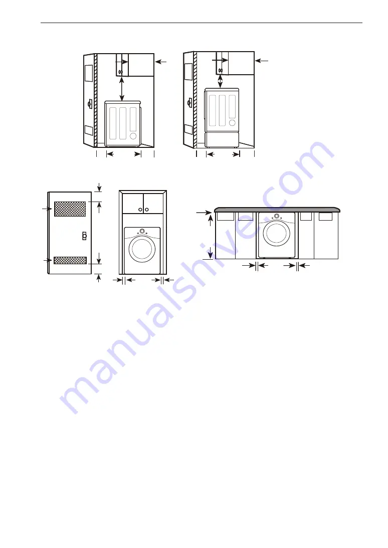
Clearances
1"*
(25 mm)
14" max.*
(356 mm)
18" min.*
(457 mm)
14" max.*
(356 mm)
18" min.*
(457 mm)
30.2"
(765mm)
5"**
(127 mm)
1"*
(25 mm)
30.2"
(765mm)
5"**
(127 mm)
24 in.
2*
(155 cm
2
)
2*
(310 cm
2
)
3" *
(76 mm)
48 in.
3" *
(76 mm)
1"
(25 mm)
1"
(25 mm)
27"
(686 mm)
0"
(0 mm)
39"
(990 mm)
1"
(25 mm)
1"
(25 mm)
27"
(686 mm)
Closet Door
Vent Requirements
Installation Spacing for Recessed Area or Closet Installation
The following spacing dimensions are recommended for this dryer. This dryer has been tested for clearances of
1 inch (2.5 cm) on the sides and rear. Recommended clearances should be considered for the following reasons:
•
Additional clearances should be considered for ease of installation and servicing.
•
Additional clearances might be required for wall, door and floor moldings.
•
Additional clearances should be considered on all sides of the dryer to reduce noise transfer.
For closet installation, with a door, minimum ventilation openings in the top and bottom of the door are
required. Louvered doors with equivalent ventilation openings are acceptable.
•
Companion appliance spacing should also be considered.
Summary of Contents for DF20WV2EW
Page 46: ...Memo ...
Page 92: ......


