3.2.1 ROTARY SWITCH AND HUMIDISTAT
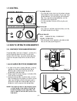
1. Remove the cabinet (Refer to section 3.1.3)
2. Disconnect all leads of rotary switch and
humidistat.
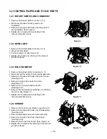
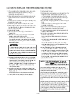
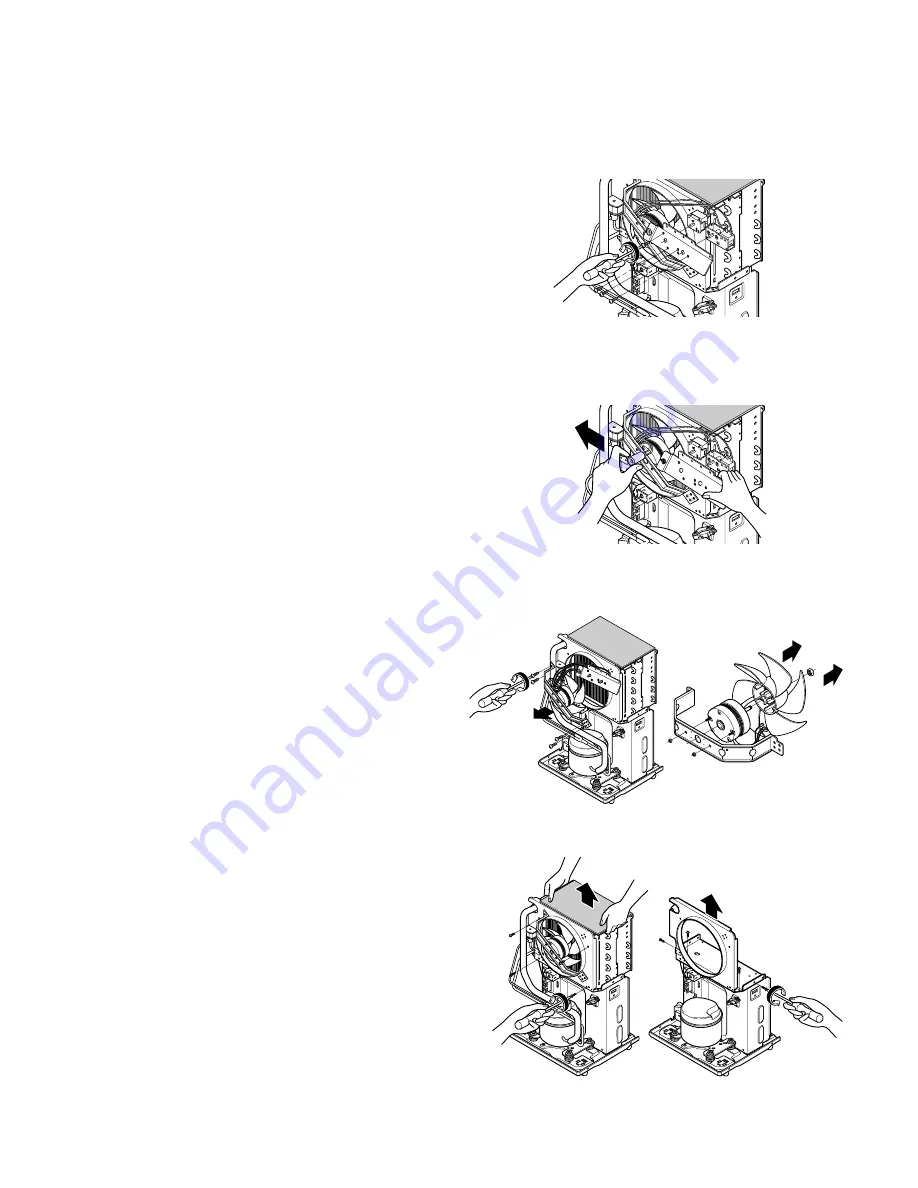
3. Remove 4 screws which fasten the rotary switch
and humidistat. (See Figure 9)
4. Replace the components by referring to the
removal procedure above.
3.2.2 NEON LAMP
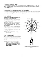
1. Remove the cabinet (Refer to section 3.1.3)
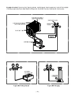
2. Disconnect two leads.
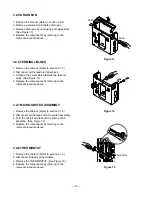
3. Pull neon lamp out. (See Figure 10)
4. Replace the cabinet by referring to the removal
procedure above.
3.2.3 FAN AND MOTOR
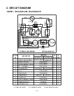
1. Remove the cabinet. (Refer to section 3.1.3)
2. Disconnect all the leads of control panel assembly.
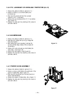
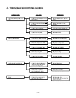
3. Remove 4 screws which fasten the motor mount.
(See Figure 11)
4. Remove 2 nuts which secure the motor.
(See Figure 11)
5. Remove one nut which fastens the fan.
(See Figure 11)
6. Remove the fan forward carefully like, as shown by
the arrow. (See Figure 11)
7. Replace the components by referring to the
removal procedure above.
3.2.4 SHROUD
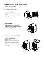
1. Remove the motor mount. (Refer to section 3.2.3)
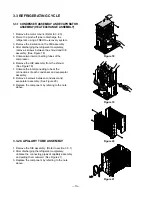
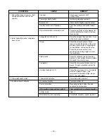
2. Remove 4 screws which fasten the H/E assembly.
(See Figure 12)
3. Remove discharge and suction tube assembly.
4. Remove 4 screws which fasten the shroud.
(See Figure 12)
5. Remove the shroud from barrier. (See Figure 12)
6. Replace the component by referring to the removal
procedure above.
—10—
3.2 CONTROL PARTS AND CYCLE PARTS
Figure 9
Figure 10
Figure 11
Figure 12


