background image

—3—

1. PREFACE

This Service Manual provides various service information, containing the mechanical and electrical parts etc. 
This dehumidifier was manufactured and assembled under the strict quality control system.
The refrigerant is charged at the factory. Be sure to read the safety precaution prior to servicing the unit.

1.1 SAFETY PRECAUTIONS

• Disconnect power supply before servicing or replacing any electrical or non-electrical component.
• Do not, under any circumstances, cut off the grounding prong or alter the plug in any manner.

1.2 FEATURES

• High efficiency
• Quiet
• Adjustable humidistat
• Hot gas defrost
• Automatic shut-off
• Water-full indicator light
• Easy roll casters
• Removable & large capacity bucket
• Washable air filter
• Fan speed: High/Low 2 fan speeds
• Drain hose connection.
• Power ON/OFF indicator light.

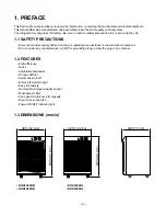
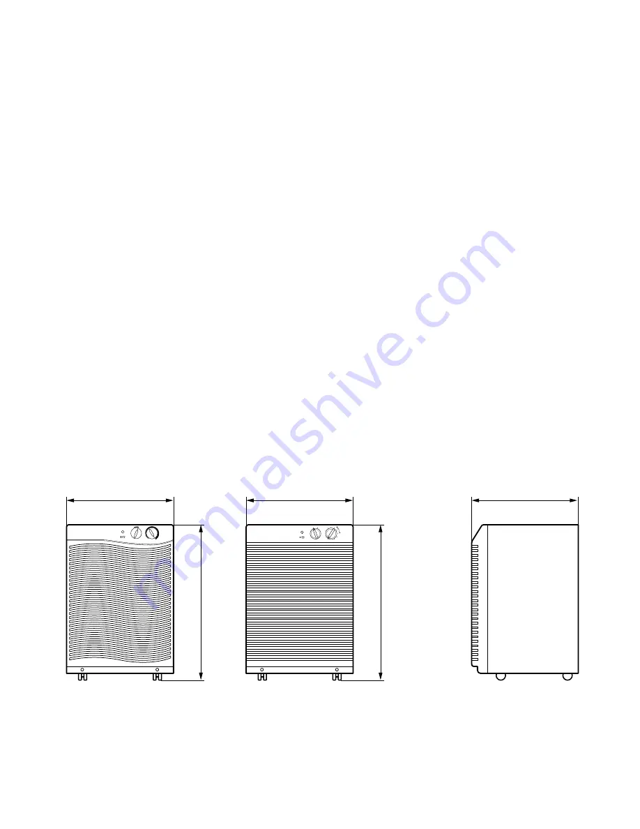
1.3 DIMENSIONS (mm/in)

320 (12 

9/16

)

340 (13 

3/8

)

530 (20 

13/16

)

320 (12 

9/16

)

530 (20 

13/16

)

High

Low

8

Humidity Control

Fan Speed

O

1

2

3

4

5

6

7

9

Max.

Lo

w

Hig

h

Fan Speed

Dryness Control

Normal

D

ry

n

e

ss

Max

O

• DHA1260HR

• DHA1260HL

• DHA1660HR

• DHA1660HL

Summary of Contents for DHA1260HL

Page 1: ...E MANUAL MODEL DHA1260HR HL DHA1660HR HL CAUTION BEFORE SERVICING THE UNIT READ THE SAFETY PRECAUTIONS IN THIS MANUAL ONLY FOR AUTHORIZED SERVICE website http www lgservice com e mail http www lgeservice com techsup html ...

Page 2: ...RONT GRILLE 9 3 1 3 CONTROL PANEL AND CABINET 9 3 2 CONTROL PARTS AND CYCLE PARTS 10 3 2 1 ROTARY SWITCH AND HUMIDISTAT 10 3 2 2 NEON LAMP 10 3 2 3 FAN AND MOTOR 10 3 2 4 SHROUD 10 3 2 5 DRAIN PAN 11 3 2 6 TERMINAL BLOCK 11 3 2 7 MICRO SWICH ASSEMBLY 11 3 2 8 THERMOSTAT 11 3 2 9 P T C ASSEMBLY OR OVERLOAD PROTECTOR O L P 12 3 2 10 COMPRESSOR 12 3 2 11 POWER CORD ASSEMBLY 12 3 3 REFRIGERATING CYCLE...

Page 3: ...rical component Do not under any circumstances cut off the grounding prong or alter the plug in any manner 1 2 FEATURES High efficiency Quiet Adjustable humidistat Hot gas defrost Automatic shut off Water full indicator light Easy roll casters Removable large capacity bucket Washable air filter Fan speed High Low 2 fan speeds Drain hose connection Power ON OFF indicator light 1 3 DIMENSIONS mm in ...

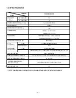
Page 4: ...SEMBLY OUTSIDE DIMENSIONS W x H x D mm in OVERLOAD PROTECTOR NOTE Specifications are subject to minor change without notice for further improvement 12 6 1ø 220 240V 50Hz R134a 170 OPEN 8 C 1 5 C CLOSE 3 C 1 5 C CONTROL RANGE 20 80 RH NORMAL SETTING 42 5 RH NR45HAEG P330MC MRA12091 9010 33 Ω TI No 4TM213SFB OPENING TEMP 135 C CLOSING TEMP 61 C TRIP CURRENT 60 C 1 7 2 1A 20A 125 250VAC 4P 19 23W 0 1...

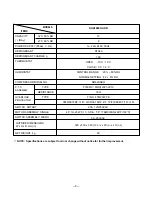
Page 5: ...TSIDE DIMENSIONS W x H x D mm in OVERLOAD PROTECTOR NOTE Specifications are subject to minor change without notice for further improvement 16 8 1ø 220 240V 50Hz R134a 190 OPEN 10 C 2 C CLOSE 5 C 2 C CONTROL RANGE 20 80 RH NORMAL SETTING 42 5 RH NR62HAEG P330MC MRA12091 9010 33 Ω TI NO 4TM232VFB OPENING TEMP 120 C CLOSING TEMP 61 C TRIP CURRENT 70 C 2 3A 20A 125 250VAC 4P 19 23W 0 11 0 13A T P 17AM...

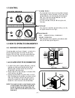
Page 6: ...rovide a better position from which to handle the bucket and help prevent icing of the coils due to colder air near the floor such as in a basement Humidity Control The Humidity Control can be set anywhere between Off and Max for normal operation If you need more dehumidification turn the Humidity Control toward Max If you need less dehumidification turn the Humidity Control toward Off Turn the Hu...

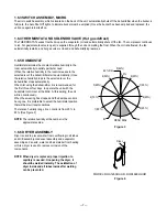
Page 7: ...rator assembly and an acid water and bad material from heating oil Also dryer is used to remove corrosion of the components NOTE When dryer is replaced proper injection to capillary is needed On opening the dryer it should be welded instantly The oxidization of dryer inside and all tubes inside after welding can be prevented 7 42 R H 40 7 30 6 35 4 50 3 60 2 70 1 80 5 42 8 25 9 20 Max O DEAD DIAL ...

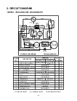
Page 8: ...S S S S S S S S S S S LOCATION NO 1 2 3 4 5 6 7 8 9 10 11 12 DESCRIPTION POWER CORD ASSEMBLY SWITCH ROTARY MOTOR ASSEMBLY SINGLE P T C ASSEMBLY COMPRESSOR O L P LAMP NEON THERMOSTAT HUMIDISTAT SWITCH ASSEMBLY MICRO TERMINAL BLOCK SOLENOID COIL DHA1260HL HR DHA1660HL HR 2H01159Y 6411A20001B 6600A20001A 4681A20002D 6748C 0003C 5416A20009A 5416A20009B 6750C 0005M 6912A30001B 2H01127E 2H01127F 5216A20...

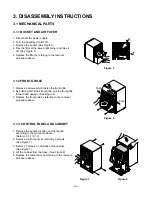
Page 9: ...nt grille pull the front grille forward and upward See Figure 6 3 Replace the front grille by referring to the removal procedure above 3 1 3 CONTROL PANEL AND CABINET 1 Remove the bucket air filter and front grille according to the procedure above Refer to 3 1 1 3 1 2 2 Remove control panel by removing 3 screws See Figure 7 3 Remove 7 screws on all sides of the cabinet See Figure 7 4 Lift the cabi...

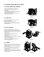
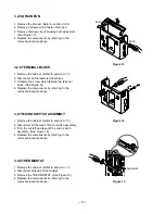
Page 10: ...s of control panel assembly 3 Remove 4 screws which fasten the motor mount See Figure 11 4 Remove 2 nuts which secure the motor See Figure 11 5 Remove one nut which fastens the fan See Figure 11 6 Remove the fan forward carefully like as shown by the arrow See Figure 11 7 Replace the components by referring to the removal procedure above 3 2 4 SHROUD 1 Remove the motor mount Refer to section 3 2 3...

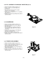
Page 11: ...gure 14 4 Replace the components by referring to the removal procedure above 3 2 7 MICRO SWITCH ASSEMBLY 1 Remove the cabinet Refer to section 3 1 3 2 Disconnect all the leads of micro switch assembly 3 Turn the nut left and take off the micro switch assembly See Figure 14 4 Replace the components by referring to the removal procedure above 3 2 8 THERMOSTAT 1 Remove the cabinet Refer to section 3 ...

Page 12: ...tely unbrace the suction and discharge tubes at the compressor connections 4 Remove the nuts and washers which fasten the compressor See Figure 16 5 Remove the compressor See Figure 16 6 Replace the component by referring to the removal procedure above 3 2 11 POWER CORD ASSEMBLY 1 Remove the cabinet Refer to section 3 1 3 2 Remove a screw which fastens the earth wire of the power cord assembly See...

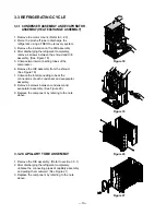
Page 13: ...Figure 19 7 Unbrace the interconnecting tube at the connections of each condenser and evaporator assembly 8 Remove 4 screws between condenser and evaporator assembly See Figure 20 9 Replace the component by refering to the note above 3 3 2 CAPILLARY TUBE ASSEMBLY 1 Remove the H E assembly Refer to section 3 3 1 2 After discharging the refrigerant completely unbrace the connecting pipes of capillar...

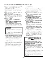
Page 14: ...the manifold connection 3 Open valve A and allow the proper charge to enter the system Valve B is still closed 4 If more charge is required the high side will not take it Close valve A 5 With the unit running open valve B and add the balance of the charge a Do not add the liquid refrigerant to the Low side b Watch the Low side gauge allow pressure to rise to 30 lbs c Turn off valve B and allow pre...

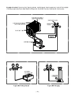
Page 15: ...e A B COMPRESSOR CAPILLARY TUBE COMPOUND GAUGE MANIFOLD GAUGE SEE INSETS BELOW CONDENSER ASSEMBLY HIGH PRESSURE SIDE EVAPORATOR ASSEMBLY LOW PRESSURE SIDE EXTERNAL VACUUM PUMP CHARGING CYLINDER HI LOW A B A B C A B CAPILLARY TUBE COMPOUND GAUGE MANIFOLD GAUGE SEE INSETS BELOW CONDENSER ASSEMBLY HIGH PRESSURE SIDE EVAPORATOR ASSEMBLY LOW PRESSURE SIDE COMPRESSOR Figure 22A Pulling Vacuum Figure 22B...

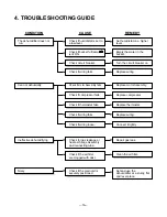
Page 16: ...ce wiring Check if the main unit is securely positioned Check for gas leakage at heat exchange Assembly and connecting tube Set and use the dehumidifier at a sturdy flat and level place Clean the air filter Check if the air filter are clogged with dust Check if motor Assembly fails Replace motor Assembly Check if compressor fails Replace compressor Check if thermostat fails Replace thermostat Chec...

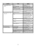
Page 17: ...to wiring diagram for terminal identification Repair or replace loose terminal It must be between 198V and 264V If not within limits call an electrician Check the wire connections If loose repair or replace the terminal If the wires are disconnected refer to wiring diagram for identification and replace the wires Check the wire connections If not according to the wiring diagram correct the connect...

Page 18: ...ose tighten it Replace compressor Tighten them If knocking sounds continue when running or loose replace the motor If the motor hums or noise appears to be internal while running replace motor assembly The bucket should be properly positioned on the hangers of the drain pan Check connection and repair Replace bucket Before removing bucket the unit should be turned off Check micro switch Check line...

Page 19: ...5 EXPLODED VIEW INTRODUCTION 19 OUTER CASE PARTS OUTER CASE PARTS CONTROL PARTS CYCLE PARTS ...

Page 20: ... 20 OUTER CASE PARTS AND CONTROL PARTS 2 7 5 8 4 1 15 9 6 3 6 3 14 13 11 10 12 MODEL DHA1260HL DHA1660HL MODEL DHA1260HR DHA1660HR 17 16 ...

Page 21: ... CYCLE PARTS AND CONTROL PARTS 21 21 20 32 36 19 30 33 18 35 34 25 26 27 ...

Page 22: ... CYCLE PARTS 22 22 23 29 24 29 24 28 31 MODEL DHA1660HL HR MODEL DHA1260HL HR ...

Page 23: ... 1 R 6600A20001A SWITCH ROTARY 1 R 5216A20001A HUMIDISTAT 1 R 6600A30003B SWITCH ASSEMBLY MICRO 1 R 2H01127F THERMOSTAT ASSY 1 R 6912A30001B LAMP NEON 1 R 6421A90001C SOLENOID COIL 1 R 4998AD2002A SHROUD 1 R 4681A20002D MOTOR ASSEMBLY SINGLE 1 R 4960AD3003A MOUNT MOTOR 1 R 5211A30195A TUBE ASSEMBLY SUCTION 1 R 5211A30194A TUBE ASSEMBLY DISCHARGE 1 R 5421A20004D EVAPORATOR ASSEMBLY 1 R 3550C 0021A ...

Page 24: ...ITCH ROTARY 1 R 5216A20001A HUMIDISTAT 1 R 6600A30003B SWITCH ASSEMBLY MICRO 1 R 2H01127E THERMOSTAT ASSY 1 R 6912A30001B LAMP NEON 1 R 6421A90001C SOLENOID COIL 1 R 4998AD2002A SHROUD 1 R 4681A20002D MOTOR ASSEMBLY SINGLE 1 R 4960AD3003A MOUNT MOTOR 1 R 5211A30195B TUBE ASSEMBLY SUCTION 1 R 5211A30194A TUBE ASSEMBLY DISCHARGE 1 R 5421A20004E EVAPORATOR ASSEMBLY 1 R 3550C 0022A COVER P T C 1 R 4H0...

Page 25: ...P No 3828A30001W Printed in China ...

Reviews: