background image

- 2 -

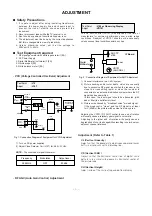
SC (Vertical “S” Correction)

Adjust so that all distance between each horizontal lines are
to be the same. 

EW (Horizontal Width)

Adjust so that digital circle pattern looks like exact circle.

EP (East-west Parabolar)

Adjust so that middle portion of the outemost left and right
vertical paralled with vertical lines of the picture tube.

EC (East-west Coner)

Adjust so that the vertical line at every 4 corners of the
screen looks like parallel with the vertical lines of the picture
tube.

ET (East-west Trapezium)

Adjust to make the length of top horizontal line same with it
of the bottom horizontal line.

Position of Blanking

1) Selection to the Mode of 4:3
2) Adjust the blanking width control (VR1701) for the same

left and right side of the picture tube.

:

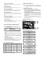
Screen & White Balance (W/B) Adjustment

NOTE : This adjustment should be preformed after screen 

voltage adjustment.

1)  Turn the TV set to receive white pattern of PAL standard

signal.

2) Adjust contrast, Brightness for 45

!

1ft-L at the center area of

screen.

3) Press Yellow button after SVC Mode on remote controller

then you can find "RG---/GG---/BG---" OSD around middle-
left of screen.

4) Set the "GG---" to "GG031".
5) Press CH (UP/DOWN) button you can find "RG---"/"BG---"

OSD around middle-left of screen.

6) Adjust volume up or down button in each status of "RG---

"/"BG---" for X=281

!

8, Y=288

!

8 with color analyzer

Table 1 : White Balance initial data

NOTE : "* " marked items don't need adjust.

:

Deflection Data Adjustment

NOTE: To enter SVC mode, press "SVC" button on the Remote

control or "OK" button on both TV set and the Remote
control.

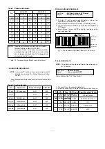
1. Deflection Adjustment Flow

1)  At deflection adjustment mode, select FUBK signal.

And then, deflection data adjustment OSD displays and at
the left top of its auto detected field frequency and deflection
adjustment mode are displayed.

2)  Press "Yellow" button and at deflection adjustment mode

(press "

DE

/

FG

" button) adjust with 50Hz 16:9 mode and

the other mode data are stored automatically. After finishing
adjustment at 50Hz 16:9 mode and check the adjusted data
of different mode.

3) Check the adjusted data changing 50Hz ZOOM1, ZOOM2

and 4:3 mode by pressing "ARC" button and if errors,
readjust at each mode.

Adjustment at 50Hz Wide mode

Item

RG

GG

BG

YD

PK

Range of Change

0~63

0~63

0~63

0~63

0~63

Initial Data

31

31

31

*   03

*   05

Adjustment

R-Drive

G-Drive

B-Drive

Y-Delay

Peak White Limit

Test Point 

: Observe Display

Adjust

: Screen Control of FBT

R, G, B Drive level (For SVC Mode)


16:9, 4:3

ZOOM1

ZOOM2

ZOOM1

16:9, 4:3 
ZOOM2

Top

Bottom

Vertical Size

[

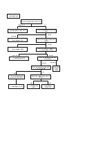
Deflection Adjustment Flowchart

Enter SVC Mode

: Press MENU button 2 times

: Press MENU button twice

Adjust deflection data, 50Hz wide mode 

Press ARC button

Adjust position of blanking

(50Hz 4:3 Mode)

Adjust deflection data

(50Hz ZOOM1, 4:3 mode)

Swap into AV mode

Return to TV mode

Adjust deflection data

(60Hz 16:9, ZOOM1, ZOOM2, 4:3 mode)

Summary of Contents for DI-28Z12

Page 1: ...SERVICE MANUAL LG DI 28Z12 MODEL ...

Page 2: ...nna distribution system where the RF signal has been amplified In this case the input signal should be attenuated with pad or filter to a satisfactory level 3 Picture noise caused by broadcast noise or weak signal If the broadcast is clean and the RF signal is at least 1mV 60dBu the picture will be noise free in any area Adjusting the VR101 RF AGC control to one end of rotation will usually cause ...

Page 3: ...ith color analyzer Table 1 White Balance initial data NOTE marked items don t need adjust Deflection Data Adjustment NOTE To enter SVC mode press SVC button on the Remote control or OK button on both TV set and the Remote control 1 Deflection Adjustment Flow 1 At deflection adjustment mode select FUBK signal And then deflection data adjustment OSD displays and at the left top of its auto detected ...

Page 4: ...le 4 CH preset Data NOTE These adjustments are possible with serviceable remote controller installed SVC button If you don t have serviceable remote controller simultaneously press OK buttons on local control and on remote controller then TV is changed from normal mode to SVC mode Item SP loud HP vol SC vol SC pres FM pres NC pres Range of Change 0 127 0 127 0 127 0 127 0 127 0 127 Initial Data 00...

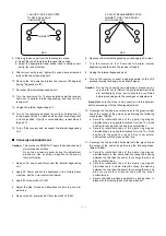
Page 5: ...ompletely forward 5 Reconnect the internal degaussing coil 6 Position the beam bender locking rings at the 9 o clock position and the other three pairs of tabs 2 4 and 6 pole magnets at the 12 o clock position 7 Perform the following steps in the order given to prepare the receiver for the purity adjustment procedure a Face the receiver in the magnetic north direction b Externally degauss the rece...

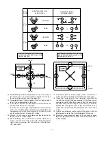
Page 6: ...g the internal degaussing coil 9 Turn on the receiver connect a signal generator to the VHF antenna terminal and apply a crosshatch signal Caution During the convergence adjustment procedure be very careful not to disturb the purity adjustment tabs are accidentally move purity should be confirmed before proceeding with the convergence adjustments Note Make sure the focus is set correctly on this i...

Page 7: ... and blue horizontal lines Fig upper right 17 Temporarily place a rubber wedge at the 5 o clock and 7 o clock positions to hold the horizontal position of the yoke 18 Check the 3 o clock and 9 o clock areas to confirm that the red and blue vertical lines are converged If the lines are not converged slightly offset the horizontal tilt of the yoke move the temporary rubber wedges if necessary to equ...

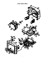
Page 8: ... 1 510 400 943 913 112 102 170 150 153 121 120 912 922 300 174 530 501 520 550 540 590 521 561 563 560 570 580 562 320 331 315 330 EXPLODED VIEW ...

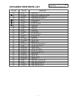
Page 9: ...0 6871VMN094A PWB ASSY MAIN 1 521 401 745E BOARD ASSY AV 530 6871VDN007A PWB ASSY DEF POWER MAIN2 540 109 548E PCB ASSY SHARP BLANK 550 6871VSN088A PWB ASSY AUDIO 560 6871VSN090A PWB ASSY LED DISPLAY 561 2075V00001A INTERNET SET TOP BOX 562 6718V00001A CARD PCMCIA SMART CARD 563 4810V00120A BRACKET MAIN 1 570 6871VSN091A PWB ASSY KEY 580 6871VSN092A PWB ASSY POWER 590 6871VSN087A PWB ASSY AV 912 3...

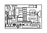
Page 10: ...T1 SKY OUT VM IH DELAY TDA4665 H BLANKING MC14538BCP STR 6709 IC801 SMPS TRANS FBT FRONT A V S VIDEO R G B Y U V AC IN MAIN S W H DRIVE H OUT V OUT LA7845 MAIN2 ASSY POWER DEFLECTION POWER IN ASSY GM71C4256 SDA5273 SDB8032 74HC373 27C512 MEGATEXT PART R G B STB U COM CXP EEPROM 24C16 CVBS MONITOR U COM INTER FACE R G B CVBS RF CVBS MONITOR CVBS A V1 CVBS U V Y RGB S W TEA5114 R G B R G B AUDIO L R...

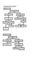
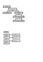
Page 11: ... Replace IC504 Open the pin5 6 SDA SCL of IC03 Check Replace FR851 D813 IC805 Check the voltage at lead of IC226 Check Replace IC809 Check all the 8V line whether short to ground If then remove it Check the waveform at pin13 of IC01 Troubleshooting Guide NO BLANKING AT 4 3 MODE Check the voltage at the pin11 of IC1701 0V 0V 5V 1 5V High Low Check Replace IC01 Check Replace IC1701 Check Replace D17...

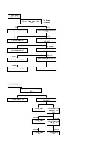
Page 12: ...3 of IC603 Normal Abnormal Check Replace IC602 Check the waveform at the pin47 of IC603 Normal Abnormal Check Replace X601 IC603 Check Replace IC102 NO COLOR Check the waveform at the pin34 of IC501 Abnormal Normal Abnormal Normal Check Replace X502 Check Replace IC501 Check the waveform at the pin29 30 of IC501 Abnormal Check Replace IC502 Check the waveform at the pin11 12 of IC501 Normal Check ...

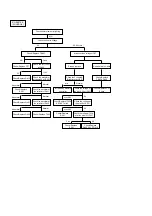
Page 13: ... B 110V at C422 Check Replace CPT Normal Abnormal Check the waveform at the collector of Q401 Check Replace IC501 0V Yes No over 0 6V over 0 6V Check the voltage at the pin39 of IC501 Check Replace IC504 SCART pin16 0V Check the voltage 7 5Vp p at the pin41 of IC501 Check Replace IC501 Normal Abnormal Check the waveform at the collector of Q402 Check Replace Q401 Normal Abnormal Check Replace T403...

Page 14: ...eplace X701 Check Replace IC501 Check the waveform at the pin6 of IC701 Check the waveform at the pin10 of IC701 No Yes Check the voltage at the pin61 62 63 of IC701 Check the voltage at the pin14 of IC501 Check Re place IC504 Abnormal Normal Check Replace Q206 Check the waveform at the pin10 11 15 I2C BUS of IC703 Check the waveform at the pin15 16 17 of IC501 Check Replace IC504 701 Check Replac...

Page 15: ...r of Q205 0V Check 5V Power line Check the voltage at the pin29 of IC102 5V Check Replace IC102 Tuner NO SKY SOUND NO SKY PICTURE CHECK SIGANAL AT P03 P202A P203A CHECK REPLACE IC201 IC01 CHECK CONECTOR P203A P202A P203A CHECK REPLACE CONECTOR P203A P202A P203A CHECK CONNECTOR POWER IN AT STB CHECK REPLACE CONNECTOR POWER IN AT STB POWER IN PCB ASSY CHECK REPLACE STB ASSY ...

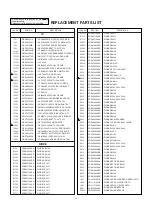
Page 16: ... 9SIP BK VIDEO OUT AM DIODE DS4148 DIODE DS4148 DIODE DS4148 DIODE DS4148 DIODE DS4148 DIODE 1S2471 DIODE 1S2471 DIODE 1S2471 DIODE 1S2471 DIODE 1S2471 DIODE 1S2471 DIODE 1S2471 DIODE 1S2471 DIODE 1S2471 DIODE 1S2471 DIODE 1S2471 LOCA NO PART NO DESCRIPTION D1712 D1713 D1714 D2901 D2902 D2904 D2906 D2907 D2908 D2909 D2910 D2911 D301 D306 D402 D406 D407 D408 D409 D410 D411 D412 D420 D501 D502 D503 ...

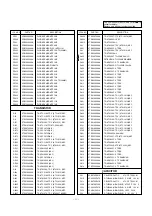
Page 17: ...CA NO PART NO DESCRIPTION Q2908 Q2909 Q2910 Q3L Q301 Q4L Q401 Q402 Q403 Q404 Q405 Q406 Q407 Q408 Q409 Q410 Q411 Q412 Q413 Q414 Q502 Q503 Q601 Q602 Q603 Q604 Q605 Q606 Q607 Q608 Q701 Q707 Q708 Q801 Q802 Q803 Q806 Q807 Q808 Q809 Q810 Q811 Q812 Q813 Q818 C01 C01K C01L C02K C02L C03K C04 0TR322709AA 0TR968000AA 0TR223800AA 0TR126609AA 0TR945009AA 0TR126609AA 0TR223800AA 0TR188700AA 0TF910000AA 0TR7330...

Page 18: ... 0 1MF 50V K C ELECTROLYTIC 100UF STD 25V M LOCA NO PART NO DESCRIPTION C1609 C1610 C1611 C1612 C1613 C1614 C1615 C1616 C1633 C1634 C1635 C1636 C1637 C1666 C1667 C1668 C1705 C1708 C1709 C1711 C1714 C18 C2S C20 C226 C227 C228 C229 C23 C230 C231 C232 C235 C237 C238 C239 C24 C240 C242 C243 C244 C245 C246 C248 C249 C25 C250 C251 C252 C253 C254 C255 C256 C257 0CE106DH618 0CQ5621N509 0CE107DH618 0CE106D...

Page 19: ... K C ELECTROLYTIC 1000UF STD 25V M LOCA NO PART NO DESCRIPTION C431 C432 C433 C434 C435 C436 C438 C440 C442 C501 C502 C503 C504 C505 C506 C507 C508 C509 C510 C511 C512 C513 C514 C515 C516 C517 C518 C519 C520 C521 C523 C524 C525 C526 C527 C528 C529 C530 C531 C532 C533 C534 C535 C536 C537 C538 C539 C540 C541 C542 C543 C544 C545 C546 0CE108DJ618 0CE108DH618 0CQ3321N509 0CX3R90K509 0CK56101515 0CE107D...

Page 20: ...EMP COMP 13P 50V J C ELECTROLYTIC 47UF STD 16V M C ELECTROLYTIC 1UF STD 50V M C TUBULA T C 27PF 50V J LOCA NO PART NO DESCRIPTION C644 C645 C646 C647 C648 C649 C652 C655 C656 C657 C658 C659 C660 C661 C662 C701 C702 C703 C704 C705 C706 C707 C708 C709 C710 C711 C713 C714 C715 C716 C717 C718 C719 C720 C721 C722 C723 C724 C725 C761 C777 C778 C779 C801 C802 C803 C804 C807 C808 C809 C810 C811 C812 C813 ...

Page 21: ... CORE FERRITE 1UH CORE FERRITE 1UH CORE FERRITE 1UH CORE FERRITE BFD3565R2F CORE FERRITE 1UH CORE FERRITE BFD3565R2F CORE FERRITE BFD3565R2F CORE FERRITE 1UH LOCA NO PART NO DESCRIPTION Z702 SK1S SK201 PJ201 P01K L01 L01K L01L L02 L02K L1S L104 L105 L106 L107 L108 L109 L111 L116 L118 L1201 L1271 L1273 L1274 L1276 L1277 L1701 L2S L202 L203 L204 L205 L206 L207 L211 L212 L217 L226 L2905 L401 L405 L50...

Page 22: ...04 R105 R106 R107 R108 R109 R11K R110 R111 R112 R117 R12K R121 R122 R123 R125 R126 R1276 R1279 R128 R1281 R1283 R1287 R1289 R1293 R1296 R13K R134 R135 R136 R14 R14K R15 R15K R16 R16K R1602 R1604 R1605 R1606 R1607 0RD0102F609 0RD3301F609 0RD0752F609 0RD2200F609 0RD2202F609 0RD3301F609 0RD2202F609 0RD2200F609 0RD3300F609 0RD6200F609 0RD1001F609 0RD1001F609 0RD1000F609 0RD2402F609 0RD5602F609 0RD3902...

Page 23: ... 1 6W 5 R CARBON FILM 100 1 6W 5 LOCA NO PART NO DESCRIPTION R248 R249 R25 R250 R251 R252 R253 R26 R27 R28 R29 R2902 R2906 R2907 R2908 R2909 R2910 R2911 R2912 R2913 R2914 R2916 R2920 R2921 R2922 R2929 R2930 R2931 R2932 R2933 R2935 R2936 R2937 R2938 R2939 R2940 R2941 R2942 R2943 R2944 R2945 R2946 R2947 R2990 R30 R304 R305 R306 R307 R308 R31 R312 R314 R315 0RD0681F609 0RD1001F609 0RD2001F609 0RD2200...

Page 24: ...FILM 1 0K 1 6W 5 R CARBON FILM 1 2K 1 6W 5 R CARBON FILM 680 1 6W 5 LOCA NO PART NO DESCRIPTION R451 R452 R453 R454 R455 R456 R457 R458 R459 R46 R460 R461 R47 R48 R50 R501 R502 R503 R504 R505 R506 R507 R508 R509 R51 R510 R512 R513 R514 R516 R517 R518 R519 R52 R520 R521 R522 R523 R524 R527 R529 R53 R530 R533 R534 R535 R536 R54 R540 R541 R542 R543 R544 R545 0RD6801F609 0RD5601F609 0RD9101F609 0RD470...

Page 25: ...CARBON FILM 3 9K 1 6W 5 R CARBON FILM 3 9K 1 6W 5 LOCA NO PART NO DESCRIPTION R633 R634 R635 R636 R637 R638 R639 R64 R640 R641 R642 R643 R644 R645 R646 R65 R66 R67 R69 R70 R701 R702 R703 R705 R706 R707 R708 R709 R711 R712 R72 R721 R737 R739 R741 R751 R766 R767 R768 R77 R777 R801 R802 R803 R804 R805 R806 R807 R808 R809 R810 R811 R813 R814 0RD3901F609 0RD3901F609 0RD1001F609 0RD1001F609 0RD2203F609 ...

Page 26: ...100 1 6W 5 R METAL FILM OXIDE 1 5K 1 2W 5 R CARBON FILM 750 1 6W 5 R CARBON FILM 470 1 6W 5 R CARBON FILM 200K 1 2W 5 R SEMI FIX H EVN DJAA03 B203 SPARK GAP RADIAL DSP 301N C04F 300V SPARK GAP RADIAL DSP 301N C04F 300V SPARK GAP RADIAL DSP 301N C04F 300V SWITCH TACT 2LEAD SWITCH TACT 2LEAD LOCA NO PART NO DESCRIPTION SW3 SW4 SW5 SW6 SW7 SW8 SW9 SW10 SW11 SW801 X501 X502 X601 X701 X702 Z01 Z03 Z101...

Page 27: ...Service Sheet of PD 8TA P N 3854VA0048A S2 1 2 DATE 98 12 04 Video CVBS Audio Chroma RGB Y Luminance V H Waveform ...

Page 28: ...Service Sheet of PD 8TA P N 3854VA0048A S1 1 2 DATE 98 12 04 ...

Page 29: ...Power Deflection ...

Page 30: ...Audio KEY AV2 ...

Page 31: ...Scart OUT Power IN CPT LED ...

Page 32: ...Main ...

Reviews: