background image

ELECTRIC & GAS DRYER

SERVICE MANUAL

CAUTION

READ THIS MANUAL CAREFULLY TO DIAGNOSE
PROBLEMS PROPERLY AND TO PROVIDE
QUALITY SERVICE SAFELY ON THESE DRYERS.

Website : http://www.lg.com

MODEL :

Electric              Gas

DLE3170W         DLG3171W

Summary of Contents for DLE3170W

Page 1: ...IC GAS DRYER SERVICE MANUAL CAUTION READ THIS MANUAL CAREFULLY TO DIAGNOSE PROBLEMS PROPERLY AND TO PROVIDE QUALITY SERVICE SAFELY ON THESE DRYERS Website http www lg com MODEL Electric Gas DLE3170W DLG3171W ...

Page 2: ...e present everywhere ESD may damage or weaken the electronic control assembly The new control assembly may appear to work well after repair is finished but failure may occur at a later date due to ESD stress એ Use an anti static wrist strap Connect wrist strap to green ground connection point or unpainted metal in the appliance OR Touch your finger repeatedly to a green ground connection point or ...

Page 3: ...1 120V AC ELECTRICAL SUPPLY 34 9 2 TEST 2 THERMISTOR TEST MEASURE WITH POWER OFF 37 9 3 TEST 3 MOTOR TEST 38 9 4 TEST 4 MOISTURE SENSOR 39 9 5 TEST 5 DOOR SWITCH TEST 40 9 6 TEST 6 HEATER SWITCH TEST ELECTRIC TYPE 41 9 7 TEST 7 GAS VALVE TEST GAS TYPE 42 10 CHANGE GAS SETTING NATURAL GAS PROPANE GAS 43 11 DISASSEMBLY INSTRUCTIONS 45 12 EXPLODED VIEW 52 12 1 CONTROL PANEL AND PLATE ASSEMBLY 52 12 2...

Page 4: ...4 1 SPECIFICATIONS See page 7 See page 8 Pedestal 1 each Purchased Separately Stacking kit 1 each Purchased Separately ACCESSORIES 0 1 2 1 0 2 ...

Page 5: ... Door Drum Child Lock Interior Light Product WxDxH Sensor Power Supply Material Finish Silver color Spray ELEC GAS 120 V 208 V 60 Hz 23 A 120 V 240 V 60 Hz 26 A 120 V 60 Hz 11 5 A 250 W 4 5 A 5400 W 22 5 A 4100 W 21 A 15 W 0 2 A 13 W 0 11 A x 2 Electronic 7 4 cu ft Electric 141 lb Gas 144 lb 8 9 5 5 Available Available Available Alcosta Available Available 27 x 30 x 38 11 16 Packing WxDxH 29 1 2 x...

Page 6: ...n the door Hold the dryer rack with both hands Put the dryer rack into the drum Check and be sure that the front of the rack is properly seated behind the lint filter 3 INSTALLATION INSTRUCTIONS Dryer Rack Installation Instructions ...

Page 7: ...t use a stacking kit with a gas dryer in potentially unstable conditions like a mobile home Stacking Kit Installation Instructions Place the washer firmly on a stable even and solid floor as product installation instructions describe in the owner s manual Do not attempt this alone At least two people are required to lift and position the dryer on top of a washing machine Failure to heed this warni...

Page 8: ...bly must be placed on a solid sturdy level floor for proper operation Insert the T clip of the 4 retainers into the dryer base as shown Press up on the back of the clip and pull outward to lock into place Place the dryer on the pedestal Make sure the front and back feet are in the correct positions The dryer feet will fit into the innermost positions as shown Make sure the screws on the pedestal a...

Page 9: ...ed After cutting 11 2 inches 3 8 cm from 3 other wires peel insulation back 1inch 2 5 cm Make ends of 3 wires a hook shape Then put the hooked shape end of the wire under the screw of the terminal block hooked end facing rightward and pinch the hook together and screw tightly Use the instructions under option 1 if your home has a 4 wire receptacle NEMAtype 14 30R If this type is available at your ...

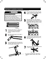
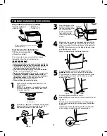
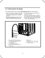
Page 10: ...10 1 2 5 cm 3 8 9 cm Option 1 0 ...

Page 11: ... for service or cleaning C B A lf your local codes or ordinances permit the connection of a frame grounding conductor to the neutral wire use these instructions If your local codes or ordinances do not allow the connection of a frame grounding conductor to the neutral wire use the instructions under 1 Connect the neutral white or center wire B to the center silver colored screw A and tighten secur...

Page 12: ...l connections securely Turn on gas and check all pipe connections internal and external for gas leaks with a non corrosive leak detection fluid 5 For LP Liquefied Petroleum gas connection refer to section on Gas Requirements For further assistance refer to section 1 New Stainless Steel Flexible Connector Use only if allowed by local codes Use Design A G A Certified Connector 2 1 8 NPT Pipe Plug fo...

Page 13: ...y Saver option is turned on by default in the Cotton Normal cycle Turn Off the Energy Saver option for a faster Normal cycle which begins with heated drying To turn the Energy Saver default off press and hold the Wrinkle Care button for three seconds ON or OFF appears in the display 4 DRYER CYCLE PROCESS 13 ...

Page 14: ...case Hi limit Electric type 3 Outlet Thermostat Auto reset Check Top Marking N85 Measure resistance of terminal to terminal Open at 185 85 Close at 167 75 Same shape as thermal cut off Resistance value Blow housing Safety Electric type 4 Lamp holder Measure resistance of terminal to terminal Resistance value 80 100 6 Idler switch Measure resistance of the following terminal COM NC 1 Lever open 2 L...

Page 15: ... of terminal to terminal Temperature condition Resistance value 10 Heater case Hi limit Electric type 9 Motor See Page 17 10 Gas valve valve 1 valve 2 Measure resistance of the following terminal Valve 1 terminal Valve 2 terminal Gas type 11 Igniter Measure resistance of terminal to terminal Resistance value 50 800 Gas type 12 Flame Detect Measure resistance of terminal to terminal Resistance valu...

Page 16: ...esistance of terminal to terminal Open at 203 Close at 158 Resistance value Gas type Gas funnel 14 Outlet Thermostat Manual reset Check Top Marking N110 Measure resistance of terminal to terminal Open at 230 110 Manual reset Resistance value Gas type Gas funnel 16 ...

Page 17: ... On Off by Centrifugal Switch STOP MODE When Motor does not operate RUN MODE Motor operates When checking component be sure to turn power off then do voltage discharge sufficiently NOTE Centrifugal switch Centrifugal switch Pull Drive forward ...

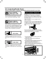
Page 18: ...18 GN YL 3 WIRE SYSTEM EARTH 4 WIRE SYSTEM X1 X2 CN11 CN11 X1 X2 7 WIRING DIAGRAM ...

Page 19: ...19 P N EBR64094887 Electric EBR64094888 Gas Main PCB Picture Electric Tab relay Black Tab relay White YL3 BL2 NA4 NA6 Gas Tab relay Black YL3 BL2 NA4 BL3 NA6 ...

Page 20: ...on alerts you to the need of cleaning the duct When the alarm about Duct clogging is on display of the panel your duct vents should be cleaned by yourself or serviceman The FlowSenseTM display consists of four bars inside a box The display has only 2 possible displays as shown here Also see the figure shown below No bars displayed 4 bars displayed 8 1 Flow sensor Flow Sensor Function 4 Bars NO Bar...

Page 21: ...uenceactivatesthe installation test Thecode will displayif the activationissuccessful 3 PressSTART PAUSEbutton Thedryerwill startthe test whichwill lastabout two minutes Theheatwill beturnedon andthe temperaturesin the drum will bemeasured 4 Checkthe display for results Duringthe testcycle monitor the FLOWSENSE TM displayon the control panel If no barsaredisplayed whenthe cycleends the exhaustsyst...

Page 22: ...hedryer clean and free of clutter Chec kthe vent hood for damage or lint clogging Make suretheareaaround the venthood is c lear FLOW SENSE TM indicator sho ws four bars during the drying cycle or thedisplay drying many turns restrictions ductwork due to lint buildup or debris restriction in the external dryer venting Install ashorter or stra ighter duct run Seethe Instructions Ductwork should be c...

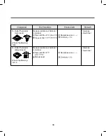
Page 23: ...23 8 4 Troubleshooting with Error ...

Page 24: ...24 ...

Page 25: ...25 ...

Page 26: ...26 ...

Page 27: ...27 ...

Page 28: ...28 ...

Page 29: ...29 ...

Page 30: ...30 ...

Page 31: ...r off OO Motor runs Displays Moisture Sensor Operation If moisture sensor is contacted with damp cloth The display number is below180 in normal condition 239 Low moisture 30 High moisture Current Temp 5 70 Current Temp 5 70 Electric control Temperature sensor ELECTRIC TYPE Motor Heater1 2700W GAS TYPE Motor ELECTRIC TYPE Motor Heater1 Heater2 5400W GAS TYPE Motor Gas valve Once Motor Controller Mo...

Page 32: ... 125V AC YES NO Check the fuse or circuit breaker Check if the voltage measured between Connector BK2 or WH2 ၃ Black Wire Linked to the Controller and WH1 ၂ White Wire Is 110 125V YES NO 1 1 2 BK2 or WH2 WH1 BK WH Check if Power Cord is properly connected Reconnect the controller Replace controIler ၂ Check if the Controller wire is disconnected ၃ Check if Terminal Block and Power Cord are connecte...

Page 33: ... Between Harness wire and tap relay Black Housing Black tap relay Check the Matching color Between Harness wire and tap relay White Housing White tap relay White Low Extra Low Low Extra Low on on on on on O O O O on off off Temperature Control below 68ᴦ 4 Turn on Heater1 and Heater2 Temperature Control below 52ᴦ 4 Only Turn on Heater1 Temperature Control below 70ᴦ 4 Turn on Burner PCB ASSEMBLY LAY...

Page 34: ...ondition Of operation 1 Black and White Housing Off Off Power Off Wire ڹ ں CROSS Items Case Heater1 Operation black Heater2 operation White PCB condition Of operation Improper connection of the heater can damage the heater or the main board CAUTION Connector Housing Black Check the Matching color Between Harness wire and Tab Relay Color Table 2 Connection of Tab Relay with PCB ASSEMBLY Gas Table1 ...

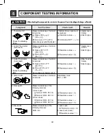
Page 35: ...35 Test 2 Thermistor Test Measure with Power Off ...

Page 36: ...36 Test 3 Motor Test ...

Page 37: ...37 6AIJ ...

Page 38: ...38 Test 5 Door switch test ...

Page 39: ...39 Test 6 Heater switch test Electric Type ...

Page 40: ...40 ᅐ Test 7 GAS Valve test Gas Type ...

Page 41: ...tents Orifice Dia 1 47mm for Propane Gas Conversion Label Instruction Sheet NCU PCK ၂ Remove 2 screws ၃ Disassemble the pipe assembly ၄ Replace Natural Gas orifice with Propane Gas orifice Opened Closed Full open Adjustment screw Close Adjustment screw Orifice Initially Warning The burner is set for natural gas at the factory The propane orifice conversion kit is sold as a service part to autheriz...

Page 42: ...42 GAS IGNITION START GAS IGNITION ON ON OFF OFF ON CLOSE VALVE 1 IGNITER VALVE 2 FLAME DETECT OPEN GAS VALVE STRUCTURE Adjustment Screw ᅐ GAS VALVE FLOW NO NO YES YES ...

Page 43: ...from its electrical supply Protect your hands and arms from sharp edges when working To reduce the risk of injury to persons adhere to all industry recommended safety procedures including the use of long sleeved gloves and safety glasses Failure to do this could lead to a serious injury W WA AR RN NI IN NG G THE DRYER TOP PLATE IS VERY LARGE AND HEAVY Fallure to follow instructions can result in d...

Page 44: ...ssemble the control panel assembly W WA AR RN NI IN NG G When you disassemble the control panel be sure to disconnect the dryer from its electrical supply Protect your hands and arms from sharp edges when working To reduce the risk of injury to persons adhere to all industry recommended safety procedures including the use of long sleeved gloves and safety glasses Failure to do this could lead to a...

Page 45: ...harness of door switch W WA AR RN NI IN NG G When you disassemble the door switch connector be sure to disconnect the dryer from its electrical supply Protect your hands and arms from sharp edges when working To reduce the risk of personal injury adhere to all industry recommended safety procedures including the use of long sleeved gloves and safety glasses Failure to do so can cause serious injur...

Page 46: ...to disconnectthedryerfromitselectricalsupply Protectyour handsandarmsfromsharpedgeswhenworking Toreducethe riskofinjurytopersons adheretoallindustryrecommended safetyproceduresincludingtheuseoflongsleevedglovesand safetyglasses Failuretodothiscouldleadtoaseriousinjury ...

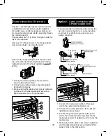
Page 47: ...47 DRYER EXHAUST CHANGE 1 2 3 4 5 Note ...

Page 48: ...emove the Cabinet Cover and Tub Drum Front assembly 3 Remove the Drum assembly 4 Remove 2 screws and cover Air guide 5 Remove the bolt and washer 1 Open the top plate 2 Remove the Cover Cabinet and Tub Drum Front assembly 3 Remove the Drum assembly 4 Remove 7 screws 5 Pull theTub Drum Rear assembly Towards the front 6 Remove the fan 7 Disconnect the motor clamp and motor ...

Page 49: ...e 2 Remove 2 screws 3 Remove the air duct 1 Disassemble the top plate 2 Remove the Cover Cabinet and Tub Drum Front assembly 3 Remove the Drum assembly and Tub Drum Front assembly 4 Disconnect the Air duct from the Tub Drum Front assembly 5 Remove the rollers from the Tub Drum Front assembly and Tub Drum Rear assembly ...

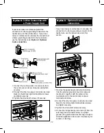
Page 50: ...12 EXPLODED VIEW 50 12 1 Control Panel and Plate Assembly A210 A211 A130 A120 A140 A110 ...

Page 51: ...51 12 2 1 Cabinet and Door Assembly Electric Type A560 A570 A530 A525 A540 A520 A600 A500 A131 A800 A610 A400 A420 A430 A390 A320 A310 A305 A300 A450 A460 A410 A330 A325 A308 A550 ...

Page 52: ...52 12 2 2 Cabinet and Door Assembly Gas type A390 A530 A525 A540 A520 A800 A600 A510 A500 A131 A550 A400 A420 A430 A330 A320 A310 A305 A300 A450 A460 A410 A325 A308 ...

Page 53: ...lectric Type K120 K100 K130 K222 K221 K224 K350 K240 F110 F120 F130 K210 K540 K230 K510 K515 K520 K251 K251 K250 K530 K600 K650 F140 K640 K660 K655 K560 K620 K310 K400 K140 F200 K250 K330 K550 K610 K651 K340 K335 K360 K336 K320 K145 K338 ...

Page 54: ...30 K222 K221 K350 K240 M160 M171 M170 M140 K210 K540 K230 K510 K520 K251 K360 K251 K250 K530 K600 K650 M141 M110 M250 M230 M190 M181 M150 M240 M220 K640 K660 K560 K620 K140 K250 K550 K610 K651 M210 M180 K330 K310 K340 K400 F200 K515 K655 K335 K336 K224 K320 ...

Page 55: ...APR 2016 PRINTED IN KOREA P No MFL62119987 ...

Reviews: