


11
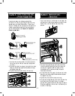
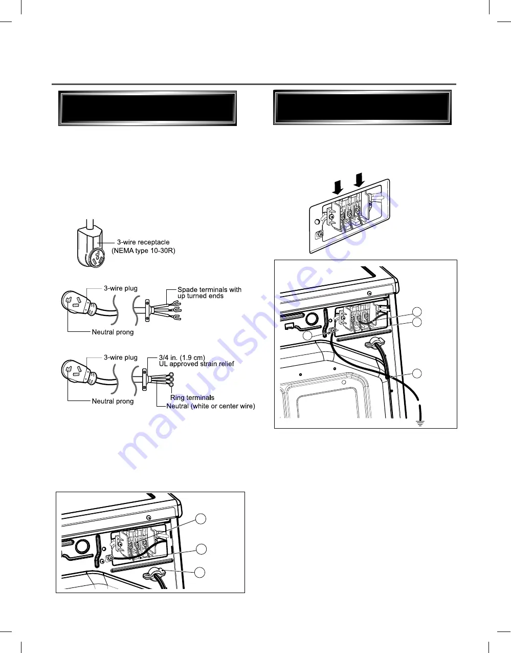
1. Remove the appliance ground wire (D) (white)
from the external ground connector screw and
reconnect it, together with the center, white,
neutral wire (E) to the center, silver colored,
terminal block screw.
2. Connect the other two power cord wires (red and
black) to the left and right terminal block screws
and tighten securely.
3. Tighten the strain relief screws securely.
4. Connect an independent ground wire (F) from the
external ground connector screw to a proper
ground. (The ground wire must be long enough to
allow the appliance to be moved, if necessary, for
service or cleaning.)
C
B
A
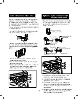
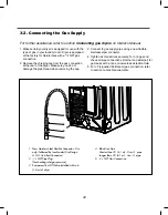
lf your local codes or ordinances permit the
connection of a frame-grounding conductor to the
neutral wire, use these instructions. If your local
codes or ordinances do not allow the connection of
a frame-grounding conductor to the neutral wire,
use the instructions under
1. Connect the neutral (white or center) wire (B) to
the center, silver colored, screw (A) and tighten
securely.
2. Connect the other two power cord wires (red and
black) to the left and right terminal block screws
and tighten securely.
3. Tighten the strain relief screws (C) securely.
Option 2
¥ If your local codes or ordinances do not allow the
connection of a frame-grounding conductor to the
neutral wire, use the instructions under this
section.
E
A
D
F
Option 3
Summary of Contents for DLE3170W
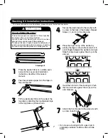
Page 10: ...10 1 2 5 cm 3 8 9 cm Option 1 0 ...
Page 18: ...18 GN YL 3 WIRE SYSTEM EARTH 4 WIRE SYSTEM X1 X2 CN11 CN11 X1 X2 7 WIRING DIAGRAM ...
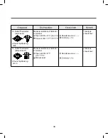
Page 23: ...23 8 4 Troubleshooting with Error ...
Page 24: ...24 ...
Page 25: ...25 ...
Page 26: ...26 ...
Page 27: ...27 ...
Page 28: ...28 ...
Page 29: ...29 ...
Page 30: ...30 ...
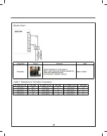
Page 35: ...35 Test 2 Thermistor Test Measure with Power Off ...
Page 36: ...36 Test 3 Motor Test ...
Page 37: ...37 6AIJ ...
Page 38: ...38 Test 5 Door switch test ...
Page 39: ...39 Test 6 Heater switch test Electric Type ...
Page 40: ...40 ᅐ Test 7 GAS Valve test Gas Type ...
Page 47: ...47 DRYER EXHAUST CHANGE 1 2 3 4 5 Note ...
Page 50: ...12 EXPLODED VIEW 50 12 1 Control Panel and Plate Assembly A210 A211 A130 A120 A140 A110 ...


