


9
DIAGNOSTIC TEST
31
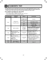
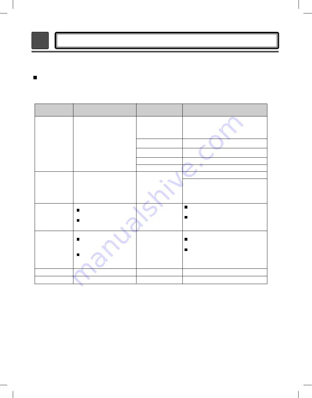
ACTIVATING THE DIAGNOSTIC TEST MODE
1. UNIT must be in standby (unit plugged in, display off)
2. Press POWER while pressing MORE TIME and LESS TIME simultaneously.
3. Press START/PAUSE button to advance through diagnostics.
1. This TEST should be used for Factory test /Service test. Do not use this DIAGNOSTIC TEST other than specified.
2. Activating the Heater manually with the Door open may trip the Thermostat attached to the Heater, therefore do not
activate it manually. (Do not press the door switch to operate the heater while the door is open )
Pressing the
START/PAUSE
None
Standard
Thermistor open
tE1
Thermistor shorted
tE2
Power off
OO
Motor runs
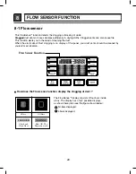
Displays Moisture Sensor Operation
If moisture sensor is contacted with
damp cloth. The display number is
below180 in normal condition
239 = Low
moisture
30 = High
moisture
Current Temp.
(5~70)
Current Temp.
(5~70)
Electric control
&
Temperature sensor
ELECTRIC TYPE
Motor+Heater1(2700W)
GAS TYPE
Motor
ELECTRIC TYPE
Motor+Heater2
(5400W)
GAS TYPE
Motor+Gas valve
Once
Motor+Controller
Motor, Heater off
Loads off, Controller off
Twice
3 times
4 times
5 times
CHECKING
ACTION
DISPLAY
CHECKPOINT
ELECTRIC TYPE Heater 1 is
energized - 2700 W
GAS TYPE is not opened
(Temperature in the drum is
displayed in degrees C.)
ELECTRIC TYPE: Heater 1 and
heater 2 are energized - 5400 W
GAS TYPE: Gas valve is energized
(Temperature in the drum is
displayed in degrees C.)
1nEd (Electric Dryer)
1ngd (Gas Dryer)
U0#
d0#
Main program Version
Display program Version
Summary of Contents for DLE3170W
Page 10: ...10 1 2 5 cm 3 8 9 cm Option 1 0 ...
Page 18: ...18 GN YL 3 WIRE SYSTEM EARTH 4 WIRE SYSTEM X1 X2 CN11 CN11 X1 X2 7 WIRING DIAGRAM ...
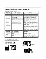
Page 23: ...23 8 4 Troubleshooting with Error ...
Page 24: ...24 ...
Page 25: ...25 ...
Page 26: ...26 ...
Page 27: ...27 ...
Page 28: ...28 ...
Page 29: ...29 ...
Page 30: ...30 ...
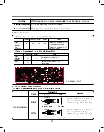
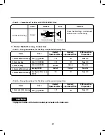
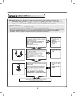
Page 35: ...35 Test 2 Thermistor Test Measure with Power Off ...
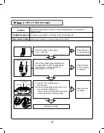
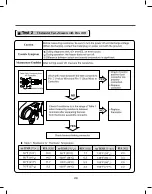
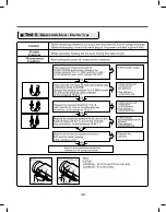
Page 36: ...36 Test 3 Motor Test ...
Page 37: ...37 6AIJ ...
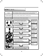
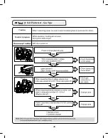
Page 38: ...38 Test 5 Door switch test ...
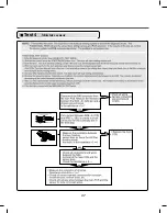
Page 39: ...39 Test 6 Heater switch test Electric Type ...
Page 40: ...40 ᅐ Test 7 GAS Valve test Gas Type ...
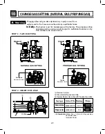
Page 47: ...47 DRYER EXHAUST CHANGE 1 2 3 4 5 Note ...
Page 50: ...12 EXPLODED VIEW 50 12 1 Control Panel and Plate Assembly A210 A211 A130 A120 A140 A110 ...


