38
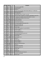
IC701 CXD3030R
•
Pin Description
Pin No.
Symbol
I/O
Description
1
AVS6
Analog GND
2
SAO
O
Analog
DAC analog output of Sled filter
3
TAO
O
Analog
DAC analog output of Tracking filter
4
FAO
O
Analog
DAC analog output of Focus filter
5
BSSD
I
Constant current input for DAC analog of servo filter
6
AVD6
Analog power supply (2.5V)
7
VSIO0
Digital GND
8
RMUT
O
1, 0
Audio DAC, zero detecting block for R Channel
9
LMUT
O
1, 0
Audio DAC, zero detecting block for L Channel
10
DCUT
O
1, 0
Digital Out
11
SSTP
I
Disc inner periphery detection signal input
12
MDP
O
1, Z, 0
Output for spindle motor servo control
13
PWMI
I
External input of spindle motor
14
DFCT
I/O
1, 0
Defect signal input/output
15
ATSK
I
Pin for Anti-shock
16
MNT0
O
1, 0
MNT0 output signal
17
MNT1
O
1, 0
MNT1 output signal
18
MNT2
O
1, 0
MNT2 output signal
19
MNT3
O
1, 0
MNT3 output signal
20
VDC0
Digital power supply (2.5V)
21
XRST
I
System reset “L” for resetting
22
VSC0
Digital GND
23
MTST0
I
Normally “H”
24
MTST1
I
Normally “L”
25
XPLCK
O
1, 0
XPLCK Signal output
26
VDIO0
Digital power supply (3.3V)
27
WFCK
O
1, 0
WFCK Signal output
28
RFCK
O
1, 0
RFCK Signal output
29
LOCK
I/O
1, 0
LOCK Signal input/output
30
AVD2
Analog power supply (2.5V)
31
IGEN
I
Resistor connection pin of current source reference for OP Amp
32
AVS2
Analog GND
33
ADIO
O
Analog
Op Amp output
34
RFDC
I
RF signal input
35
CE
I
Center servo analog input
36
TE
I
Tracking error signal input
37
SE
I
Slide Error input


