


ENGLISH
8
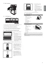
Standing bracket_1
5(6
8+
3ULPH
'ULO
O7
HP
SODW
H
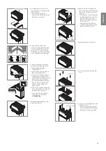
Standing bracket 1
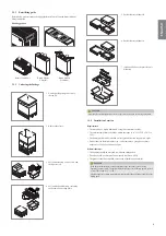
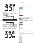
3.
5HPRYHWKH'ULOOWHPSODWHDQG¿[WKH
Standing bracket 1 on the wall.
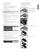
Battery Module B
Label
Wall
Rear
Front
Front
Rear
Battery Module Direction
4. Place Battery Module B on the rear
side of Module Connect plate.
* The side without bolts is the front
of the Battery Module.
*
&KHFNWKHODEHOWRFRQ¿UPWKH
battery pack is of B. Label is
attached on the left side of Battery
Module.
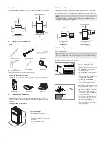
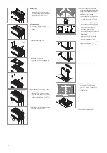
Battery Module A
Label
Front
Front
Battery Module B
Battery Module A
TOP VIEW
Rear
Front
Wall
5. Place Battery Module A on the front
side of Module Connect plate. The
Rear side of each Battery Module
should face each other. After that,
remove the Spacer between the wall
and Battery Module.
*
&KHFNWKHODEHOWRFRQ¿UPWKH
Battery pack is of A. Label is
attached on the left side of Battery
Module.
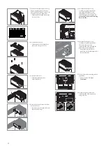
Module Support BRKT
6. Assemble Module Support BRKTs
using 6 bolts each.
* Tighten the M6 Flange Bolts (x12)
with a torque of 5N·m.
Plac
e the spac
er
In the line HERE
Plac
e the s
pac
er
In the line HERE
Plac
e the s
pac
er
In the
line
HERE
Plac
e th
e spac
er
In the line H
ERE
Plac
e th
e spac
er
In the line H
ERE
Plac
e the s
pac
er
In t
he line HERE
Plac
e the s
pac
er
In t
he line HERE
Plac
e th
e spac
er
In t
he line H
ERE
Plac
e th
e spac
er
In t
he line H
ERE
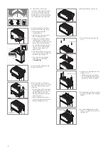
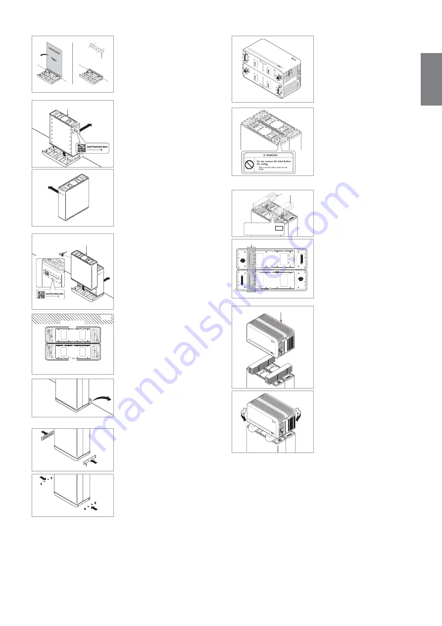
Battery Control Unit
Battery Modules
7. Remove bubble wrap from
connectors of Battery Control Unit
and the warning label of Battery
Modules.
Plac
e th
e spac
er
In the line H
ERE
Plac
e th
e spac
er
In the line H
ERE
Plac
e th
e sp
ace
r
In the l
ine
HERE
Plac
e th
e sp
ace
r
In the l
ine
HERE
Plac
e the s
pacer
In the line
HERE
Plac
e the s
pacer
In the line
HERE
Plac
e the sp
acer
In t
he li
ne HE
RE
Plac
e the sp
acer
In t
he l
ine
HE
RE
Spacer
(used for assmbly ang disassembly)
TOP
Plac
e the spac
er
In
the line HERE
Plac
e the spac
er
In
the line HERE
Plac
e the s
pac
er
In
th
e lin
e HERE
Plac
e the spac
er
In
the line HERE
Plac
e the spac
er
In
the line HERE
Spacer
Spacer
TOP VIEW
8. Place the spacers on the position
marked with label on Battery
Modules.
Plac
e the spac
er
In the l
ine
HERE
Plac
e the spac
er
In the l
ine
HERE
Plac
e the spac
er
In th
e line HE
RE
Plac
e the spac
er
In th
e line HERE
Plac
e the
spa
cer
In t
he l
ine
HERE
Plac
e the
spa
cer
In t
he line HE
RE
Plac
e the spac
er
In t
he line H
ERE
Plac
e the spac
er
In th
e line H
ERE
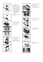
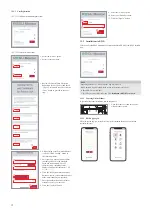
Battery Control Unit
Battery Control Unit
Plac
e the spac
er
In the li
ne H
ERE
Plac
e the spac
er
In the li
ne HERE
Plac
e the spac
er
In the li
ne HERE
Plac
e the spac
er
In the li
ne HERE
Plac
e the spac
er
In the line HERE
Plac
e the spac
er
In the line HERE
Plac
e the spac
er
In the line H
ERE
Plac
e the spac
er
In the line HERE
9. Place the Battery Control Unit on
top of the spacers, and align with the
Battery Module.
* Be careful not to break the
connector between the spacers and
the Battery Control Unit.


