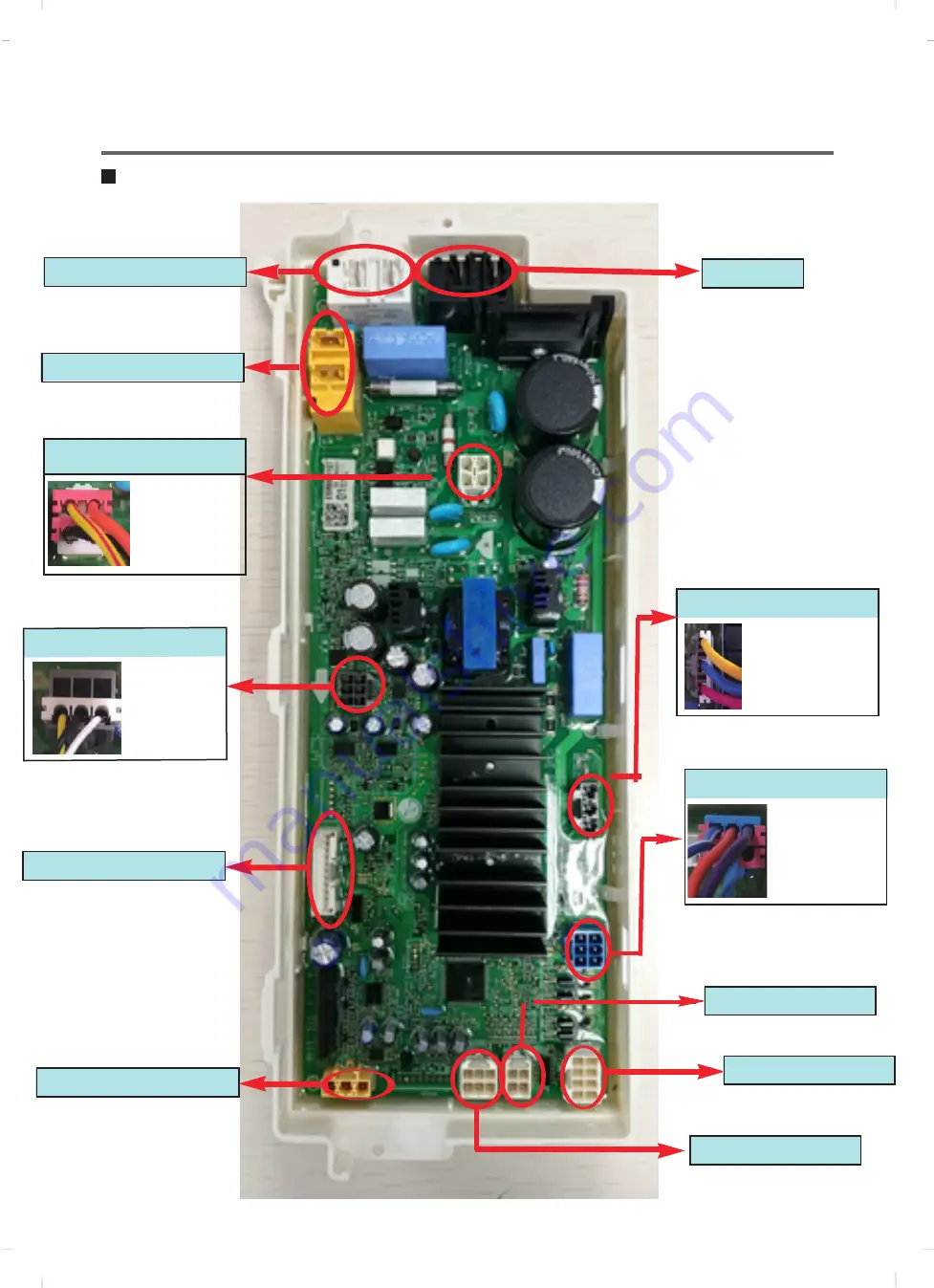
PCB Layout (Main)
Heater
Door Switch
Display
Moter Stator Control
V-U/U-W
/W-V
→R:8~11Ω
Water sensor
blue&white:thermister
blue:common
violet:pressure switch
orange:pressure switch
Drain motor
BLDC pump
white:U
black:V
yellow:W
yellow&red:door switch
black:door switch
orange:door switch
PCB POWER
19
Dry Heater
Dry Fan motor
Vibration Sensor
Thermistor
DC Valve
Summary of Contents for F V9 CP Series
Page 6: ...3 PARTS IDENTIFCATION 6 ...
Page 7: ...3 PARTS IDENTIFCATION 7 ...
Page 9: ...1 2 3 1 2 3 9 ...
Page 48: ...9 Par t i nspect i on 48 ...
Page 49: ...49 ...
Page 50: ...50 ...
Page 51: ...51 ...
Page 52: ...52 50 I II I I I II I II II I I I I I I I I I I I I I I ...
Page 67: ...65 11 4 THE EXPLODED VIEW OF DRYER M110 M120 M100 ...
Page 68: ...59 P No MFL69882928 ...


