background image

14

Ch2. Locations

„

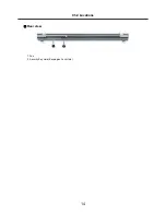
Rear view

1. Fan

2. Security Key Hole (Kensington Lock Hole)

Summary of Contents for F1

Page 1: ...0 Service Manual F1 LG Electronics ...

Page 2: ...Block Diagram Fn key combinations Status indicators BIOS Flash BIOS Setup Ch 4 Symptom to part index Power system checkout Numeric error codes Error messages LCD related symptoms Indeterminate problems Ch 5 Removing and replacing a part FRU Ch 6 Part list Part list Exploded view Contents ...

Page 3: ...er you are servicing may have been changed Be extremely careful during write operations such as copying saving or formatting If you select an incorrect drive data or programs can be overwritten Use the following strategy to prevent unnecessary expense for replacing and servicing parts 1 If you are instructed to replacing a part but the replacement does not correct the problem reinstall the origina...

Page 4: ...hrow it into fire or water or short circuit it Dispose of the battery pack as required by local ordinances or regulations Use only the battery in the appropriate parts listing when replacing the battery pack Use of an incorrect battery can result in ignition or explosion of the battery Warning If the LCD breaks and the fluid from inside the LCD gets into your eyes or on your hands immediately was ...

Page 5: ...ed covers and other parts in a safe place away from all personnel while you are servicing the machine Keep your tool box away from walk areas so that other people will not trip over it Do not wear loose clothing that can be trapped in the moving parts of a machine Make sure that your sleeves are fastened or rolled up above your elbows If your hair is long fasten it Insert the ends of your necktie ...

Page 6: ...r before 1 Performing a mechanical inspection 2 Working near power supplies 3 Removing or installing main units Before you start to work on the machine unplug the power cord If you cannot unplug it ask the customer to power off the wall box that supplies power to the machine and to lock the wall box in the off position If you need to work on a machine that has exposed electrical circuits observe t...

Page 7: ... look carefully for possible hazards in your work area Examples of these hazards are moist floors non grounded power extension cables power surges and missing safety grounds Do not touch live electrical circuits with the reflective surface of a plastic dental mirror The surface is conductive such touching can cause personal injury and machine damage Do not service the following parts with the powe...

Page 8: ...rds such as loose or missing hardware Refer to the following checklist and begin the checks with the power off and the power cord disconnected Checklist 1 Check exterior covers for damage loose broken or sharp edges 2 Power off the computer Disconnect the power cord 3 Check the power cord for a A third wire ground connector in good condition Use a meter to measure third wire ground continuity for ...

Page 9: ...he part from touching your clothing Most clothing retains a charge even when you are wearing a wrist strap 4 Use the black side of a grounded work mat to provide a static free work surface The mat is especially useful when handling ESD sensitive devices 5 Select a grounding system such as those listed below to provide protection that meets the specific service requirement Note The use of a groundi...

Page 10: ...e DVD ROM drive or the other optical storage device could result in exposure to hazardous laser radiation There are no serviceable parts inside those drives Do not open Danger Emits visible and invisible laser radiation when open Do not stare into the beam do not view directly with optical instruments and avoid direct exposure to the bean 1 5 Backup Standby RTC battery safety information When repl...

Page 11: ...cur for a variety of reasons that have nothing to do with a hard ware defect such as cosmic radiation electrostatic discharge or software errors Consider replacing a FRU only when a problem recurs If you suspect that a FRU is defective clear the error log and run the test again If the error does not recur do not replace the FRU Be careful not to replace a non defective FRU What to do first You mus...

Page 12: ...age caused foreign material in the diskette drive Diskette drive damage caused by pressure on the diskette drive cover or by the insertion of a diskette with multiple labels Damaged or bent diskette eject button Fusses blown by attachment of a non supported device Forgotten computer password making the computer unusable Sticky keys caused by spilling a liquid onto the keyboard The following sympto...

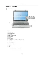
Page 13: ...utton 4 Search button 5 Wireless LAN ON OFF button 6 Built in Speakers 7 Keyboard 8 Built in microphone 9 4 in 1 SD MMC Memory Stick Memory Stick Pro Card Slot 10 Line in port 11 Microphone port 12 Headset S PDIF port 13 Touchpad button 14 Touchpad 15 LCD 16 Wireless LAN Antennas Wireless LAN is optional ...

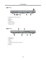
Page 14: ... Kensington Lock Hole 2 LAN Port 3 Modem ports 4 USB Port 5 Optical Disk Drive 6 Open Disk Tray button 7 Emergency Ejector 1 PCMCIA card slot 2 IEEE 1394 Port 3 USB Port 4 S Video port A 7 pin slot compatible with 4 pin S Video cables 5 VGA Port 6 Power Port ...

Page 15: ...14 Ch2 Locations Rear view 1 Fan 2 Security Key Hole Kensington Lock Hole ...

Page 16: ...ications may differ by model type LCD 15 4 WXGA Resolution 1280 x 800 TFT Color LCD Authentication for Anticopy Technology U S Patent Nos 4 631 603 4 577 216 4 819 908 4 907 093 5 315 448 and 6 516 132 Patent number of Macrovision This product includes the technologies that are possessed by Macrovision and corresponding companies and protected by the US Patent Law and other related laws Use of all...

Page 17: ...y model type DVMT Dynamic Video Memory Technology Sound Realtek High Definition Audio Codec ALC883 Built in Stereo Speakers MODEM Qcom Actiontec MD560LMI 2 RJ 11 Jack LAN Realtek RTL8111B 10 100 1000 Ethernet Controller RJ 45 Jack Weight Full Installation 2 7kg Battery About 320g Weight descriptions may differ by model type ...

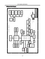
Page 18: ...s Page 28 U SB 4 B l uet oot h Page 27 M i ni _PCI E U SB 5 PATA D VD C D R O M Page 23 Page 23 H D D O Z711M P Page 24 25 1394 3 I N 1 C A R D A zal i a I nt er nal SPK M I C LI N E I N Ear phone SPD I F O ut I nt er nal M I C Page 30 B I O S Page 31 Page 31 TP K B I SA Page 34 SYS PO W ER Page 35 Page 36 M A X1999 O Z813 1_8VSU N SC 486 I SL6262 3V 5V C PU PO W ER SM D D R _VTER M C H AR G ER Pa...

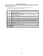
Page 19: ...me The volume can be adjusted within a 25 grade range Fn F7 Increases the LCD brightness The brightness can be adjusted within a nine grade range Fn F5 Decreases the LCD brightness The brightness can be adjusted within a nine grade range Fn F4 Switches between Touchpad Disable and Touchpad Enable The initialization takes 1 2 seconds It is recommended that you use it after initialization Fn F3 Swit...

Page 20: ...rged Blue Charged more than 90 Green Blinking Discharged Off AC adapter connected battery fully charged or removed Off Charged less than 10 Red In faulty state Red Blinking 4 Num Lock lamp Num Lock lamp is turned on when you press Num Lock key indicating the embedded numeric keys are available Num Lock lamp is turned off when you press Num Lock key again indicating the numeric keypad is not availa...

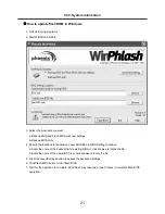
Page 21: ...nsert the diskette into the FDD of your computer 5 Boot your computer with the diskette and type phlash16 wph mode n 6 Cold boot and follow the instruction displayed on the screen Flash options mode n 0 Default mode Keep the current DMI information and update BIOS image only 1 Update DMI information only If new DMI information is not specified the current DMI information is left unchanged 2 Update...

Page 22: ...nter the name of the backup file for existing BIOS or click Browse to locate the file b Enter the name of the new BIOS file or click Browse to locate the file 5 Click Advanced Settings button to access the advanced settings 6 Click Flash BIOS button to start flash BIOS 7 Wait for the operation to complete WinPhlash may take one or two minutes to complete flash BIOS operation How to update flash RO...

Page 23: ...dated appears on the screen then the computer restarts 9 After the restart make sure the system BIOS is updated 10 If your computer does not restart automatically turn off your computer and then turn it back on by pressing power button Ch3 System information ...

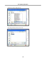
Page 24: ...age iso to each Service Centers when we have a new revision Please refer to the BIOS Table Document No SBE HA 01 for latest BIOS 2 Service center will make Bootable Image CD with Image file iso as below a Insert empty disc to CD RW Drive and start Nero Burning ROM b Select Disc Image or Saved Project ...

Page 25: ...24 Ch3 System information c Select File Format as Image Files iso d Open Image File iso which is sent from LGE ...

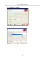
Page 26: ...25 Ch3 System information e Tab Next then burning will be started f Burn process completed as below and tab OK ...

Page 27: ...tomatically update EC first and reboot again 2 Type in Mode Name at the WIP ID then press Enter key You must use Capital Letter You can see the Model Name in ID Label at the bottom Case of PC M N LMXX XXXX 3 Type in Serial No at the WIP ID then press Enter key You must use Capital Letter You can see the Serial No in ID Label at the bottom Case of PC S N 412KIXXXXXXXX 13digits ...

Page 28: ...27 Ch3 System information 4 You can see the BIOS flash process as below 5 After flashing is completed you can see the PASS on your screen and reboot your PC ...

Page 29: ...system environment hardware configurations power saving mode etc Open the BIOS Setup Utility in the following situations 1 to change the BIOS setup 2 to replace the backup battery 3 system configuration error occurs 4 to change the boot order 5 to set change a password Press the power button When the LG logo appears on the screen press and enter the BIOS Setup Utility Ch3 System information ...

Page 30: ...ted Select Menu Move to another menu Change Values Change the value of a selected item Load Default Configuration Display Setup Confirmation window Press Enter to load default configuration Select Sub Menu Some items have sub menus Display the sub menu for a selected item Save and Exit Display Setup Confirmation window Press Enter to save and exit Exit In a sub menu press Esc to move to the previo...

Page 31: ...System Time and Date Advanced menu Configure IDE and USB settings Boot menu Set up Boot Type and Boot Sequence Ch3 System information BIOS Setup Menu Once you enter the BIOS Setup Utility the Main menu will appear on the screen The main menu displays the system information including the basic configuration ...

Page 32: ...31 Ch3 System information Security menu Install or clear Supervisor s and User s Password settings Exit menu Choose decided status before leaving the BIOS menu ...

Page 33: ...allows you to set the system time The system clock will go on no matter you shut down the PC or get into sleep mode The set format is hour minute second System Date This item allows you to set the system date The date format is day month date year Day Day of the week from Sun to Sat which is determined by BIOS read only Month The month from 01 January to 12 December Date The date from 01 to 31 Yea...

Page 34: ...rt Select Enabled to enable the legacy support for USB devices Setting options Enabled and Disabled Intel R SpeedStep tm tech This item allows you to enable or disable Intel SpeedStep technology When set to Disabled the system always operates in a conserve power mode the processor works at FSB400 600MHz or FSB533 800MHz If you want optimize the processor set this item to Enabled so that the proces...

Page 35: ...the boot up screen Settings options Disabled and Enabled The default setting is Enabled 1st 2nd and 3rd Boot Device The three items allow you to set the sequence of boot devices where BIOS attempts to load the disk operating system Ch3 System information Boot menu ...

Page 36: ...35 Change Supervisor Password Set supervisor password Change User Password Set user password Security menu Ch3 System information ...

Page 37: ...ges and Exit Exit the utility without saving the changes you have made Discard Changes Abandon your changes and reload the previous configuration before running the utility Load Optimal Defaults Select this item to load the default settings for optimal system performance Exit menu Ch3 System information ...

Page 38: ... Power off the computer 6 Disconnect the AC adapter and install the charged battery pack 7 Check that the battery pack supplies power when you power on the computer If you suspect a power problem see the appropriate one of the following power supply checkouts 1 Checking the AC adapter 2 Checking the operational charging 3 Checking the battery pack 4 Checking the backup battery Checking the AC adap...

Page 39: ...the plug of the AC adapter cable See the following figure 3 If the voltage is not correct remove the power code form AC adapter 4 10 seconds later connect the power code then measure the output voltage 5 If the voltage is not correct change the AC adapter 2 1 Ground 2 18 05 19 95 1 Voltage V dc Pin Ch4 Symptom to part index ...

Page 40: ...arge battery pack when its temperature is below 0 or above 75 Checking the battery pack 1 Open the Power Meter window by clicking Start Control Panel Power Options and then check the total power remains Battery charging does not start until the power Meter shows that less than 95 of the total power remains under this condition the battery pack can charge to 100 of its capacity This protects the ba...

Page 41: ... When this happens you can perform the full discharge charge to improve the capacity You should perform periodic full discharge charge once every 30 60 days You should always use the battery until its power is low then fully charge the battery 3 Trickle charge If the temperature of the battery pack drops below 10 the trickle charging begins The trickle charging may take 32 hours for the battery pa...

Page 42: ...the voltage is still less than 11 1 V DC after recharging replace the battery 4 If the voltage is more than 11 1 V DC measure the resistance between battery terminals 1 and 2 The resistance must be 2 to 4 typically 3 5 If the resistance is not correct replace the battery pack If the resistance is correct replace the system board Ch4 Symptom to part index Note Battery is an expendable supplier so i...

Page 43: ... NBL01 LCD Issue System Auto Power Off NBP10 System Auto Power On NBP09 Can t Power Off NBP08 System Can t Shutdown Properly NBP07 No Display NBP06 System Hang Up In BIOS Utility NBP05 System Hang Up In POST NBP04 System Hang Up During Booting NBP03 System Can t Power On NBP02 No Power NBP01 System Power Issue Others NB999 NTF From Customer Return NB998 No Trouble Found DOA NBDOA Product Issue Eng...

Page 44: ...Disc Comparability NBC07 CD ROM Breakdown NBC06 CD ROM Function Fail NBC05 CD ROM Write Error NBC04 CD ROM Read Error NBC03 CD ROM Tray Can t Be Rejected NBC02 System Can t Detect CD ROM Drive NBC01 ODD Issue English Description Code CPU Socket Fail NBCP3 CPU Breakdown NBCP2 CPU Speed Display Incorrectly NBCP1 CPU Issue Memory Slot Fail NBD04 DRAM Breakdown NBD03 System Can t Detect DRAM Module NB...

Page 45: ...o Short NBB05 Battery Breakdown NBB04 Battery s Capacity Will Down To Empty Quickly NBB03 Battery Pack Can t Charge To 100 NBB02 Battery Pack Can t Charge NBB01 Battery Pack Issue PCMCIA Function Fail NBI12 Card Reader Function Fail NBI11 IEEE 1394 Port Function Fail NBI10 The TV Output Color Is Monochromatic NBI09 S Video TV Out Port Function Fail NBI08 VGA Port Function Fail NBI07 LPT Port Funct...

Page 46: ...ia WLAN NBI28 Can t Connect To Internet Via WLAN NBI27 Wireless LAN Signal Is Weak Or Unstable NBI26 Wireless LAN Function Fail NBI25 Connect Quality Is Unstable Via RJ45 LAN Port NBI24 Can t Connect To Internet Via RJ45 LAN Port NBI23 MAC Address Is Empty NBI22 RJ45 Network Jack Function Fail NBI21 RJ11 MODEM Jack Function Fail NBI20 SPDIF Out Function Fail NBI19 Line In Jack Function Fail NBI18 ...

Page 47: ... OS NBS04 Can t Install OS NBS03 OS XP 2000 Loading Fail NBS02 Microsoft Issue Setting Bug NBS01 OS Software Driver Issue System Can t Boot After Flash KBC Firmware NBFB8 System Can t Boot Result From Flash BIOS Fail NBFB7 System Can t Boot After Flash BIOS NBFB6 KBC Firmware Version Error NBFB5 Flash KBC Firmware Fail NBFB4 Can t Flash BIOS NBFB3 BIOS Version Error NBFB2 Flash BIOS Fail NBFB1 BIO...

Page 48: ...BUP1 HW ME Parts Upgrade Issue Sticker Loose Or Damage NBM10 AC Adapter Damage NBM09 OSD Bezel Damage NBM08 Palm Rest Damage NBM07 Hinge Cover Damage NBM06 Middle Cover Damage NBM05 Lower Case D Casing Damage NBM04 Top Case C Casing Damage NBM03 LCD Bezel B Casing Damage NBM02 LCD Cover A Casing Damage NBM01 Mechanism Accessory Parts Issue Ch4 Symptom to part index ...

Page 49: ... NBR18 Battery Connector Fail NBR17 Socket Slot Damage NBR16 CD ROM Doesn t Fix To NB NBR15 Inverter Cable Damage NBR14 Inverter Damage NBR13 Connector Damage NBR12 LVDS Cable Damage NBR11 SWAP New Touchpad NBR10 SWAP New Keyboard NBR09 SWAP New Battery Pack NBR08 SWAP New WLAN Module NBR07 SWAP New CPU NBR06 SWAP New DRAM Module NBR05 SWAP New OSD NBR04 SWAP New HDD NBR03 SWAP New LCD Panel NBR02...

Page 50: ...IA Bracket NBR36 SWAP New Mechanism Parts NBR35 Blue Tooth Antenna Damage NBR34 SWAP New Blue Tooth Module NBR33 SWAP New AC Adapter NBR32 Update BIOS NBR31 CPU VGA Thermal Module Or Thermal Pad Damage NBR30 English Description Code Ch4 Symptom to part index ...

Page 51: ...RU 3 Remove or disconnected all of the following devices a Non LG devices b Printer mouse and other external devices c Battery pack d PC cards e ODD CD ROM Combo drive or FDD drive in the Bay f Hard disk drive Note Use the other memory card because it needs when operating computer 4 Power on the computer 5 Determine whether the problem has changed 6 If the problem does not recur reconnect the remo...

Page 52: ...power cords from electrical outlets remove the battery pack and then disconnect any interconnecting cables Caution Before the computer is powered on after FRU replacement make sure that all screws springs and other small parts are in place and are not loose inside the computer Verify metal flakes can cause electrical short circuits Ch5 Removing and replacing a part ...

Page 53: ...52 1010 Battery Pack 1 Push the battery latch in the direction shown below then slide the battery pack out of the slot Ch5 Removing and replacing a part ...

Page 54: ...1 1 Qty Specification FRU No No 1 Remove 2 Screws the remove the HDD Cover 2 Remove the HDD Cushion 1020 Hard Disk Drive Ch5 Removing and replacing a part Remove the following parts in order before replacing this part a Battery Pack 1010 ...

Page 55: ...54 3 Remove HDD Assembly 4 Remove 2 Screws 2 M2X0 4 4 5mm 3mm FAB30065501 1 Qty Specification FRU No No Ch5 Removing and replacing a part ...

Page 56: ...55 Ch5 Removing and replacing a part ...

Page 57: ...01 1 Qty Specification FRU No No 1 Remove 4 Screws 2 Remove the System Door Ch5 Removing and replacing a part 1020 Hard Disk Drive Remove the following parts in order before replacing this part a Battery Pack 1010 b Hard Disk Drive 1020 ...

Page 58: ...57 3 Remove the Memory Module Ch5 Removing and replacing a part ...

Page 59: ...Drive 1 M2 5X0 45P 4 5mm 5mm FAB30065101 1 Qty Specification FRU No No Ch5 Removing and replacing a part 1040 Optical Disk Drive Remove the following parts in order before replacing this part a Battery Pack 1010 b Hard Disk Drive 1020 c Memory 1030 ...

Page 60: ... the Antenna Cable 2 Remove the WLAN Card Ch5 Removing and replacing a part 1050 WLAN Card Remove the following parts in order before replacing this part a Battery Pack 1010 b Hard Disk Drive 1020 c Memory 1030 d Optical Disk Drive 1040 ...

Page 61: ...C Connector 2 Remove the MDC Card Ch5 Removing and replacing a part 1060 MDC Card Remove the following parts in order before replacing this part a Battery Pack 1010 b Hard Disk Drive 1020 c Memory 1030 d Optical Disk Drive 1040 e WLAN Card 1050 ...

Page 62: ...sconnect the Fan Assembly Cable then remove the Fan Assembly Ch5 Removing and replacing a part 1070 Fan Assembly Remove the following parts in order before replacing this part a Battery Pack 1010 b Hard Disk Drive 1020 c Memory 1030 d Optical Disk Drive 1040 e WLAN Card 1050 f MDC Card 1060 ...

Page 63: ...62 Ch5 Removing and replacing a part ...

Page 64: ...h5 Removing and replacing a part 1080 Retainer Remove the following parts in order before replacing this part a Battery Pack 1010 b Hard Disk Drive 1020 c Memory 1030 d Optical Disk Drive 1040 e WLAN Card 1050 f MDC Card 1060 g Fan Assembly 1070 ...

Page 65: ...64 Ch5 Removing and replacing a part ...

Page 66: ... Qty Specification FRU No No Ch5 Removing and replacing a part 1090 Keyboard Remove the following parts in order before replacing this part a Battery Pack 1010 b Hard Disk Drive 1020 c Memory 1030 d Optical Disk Drive 1040 e WLAN Card 1050 f MDC Card 1060 g Fan Assembly 1070 h Retainer 1080 ...

Page 67: ...66 3 Remove the Keyboard Ch5 Removing and replacing a part ...

Page 68: ...Button Sub Board Connector Ch5 Removing and replacing a part 1090 Keyboard Remove the following parts in order before replacing this part a Battery Pack 1010 b Hard Disk Drive 1020 c Memory 1030 d Optical Disk Drive 1040 e WLAN Card 1050 f MDC Card 1060 g Fan Assembly 1070 h Retainer 1080 i Keyboard 1090 ...

Page 69: ...68 3 Remove the Button Sub Board Ch5 Removing and replacing a part ...

Page 70: ...g a part 1110 Display Module Remove the following parts in order before replacing this part a Battery Pack 1010 b Hard Disk Drive 1020 c Memory 1030 d Optical Disk Drive 1040 e WLAN Card 1050 f MDC Card 1060 g Fan Assembly 1070 h Retainer 1080 i Keyboard 1090 j Button Sub Board 1100 ...

Page 71: ...70 2 Remove 2 Screws 2 M2 5X0 45P 4 5mm 5mm FAB30065101 1 Qty Specification FRU No No 3 Remove 2 Screws 2 M2 5X0 45P 4 5mm 5mm FAB30065101 1 Qty Specification FRU No No Ch5 Removing and replacing a part ...

Page 72: ...71 4 Remove the Display Module Ch5 Removing and replacing a part ...

Page 73: ... replacing a part 1120 Main Board Remove the following parts in order before replacing this part a Battery Pack 1010 b Hard Disk Drive 1020 c Memory 1030 d Optical Disk Drive 1040 e WLAN Card 1050 f MDC Card 1060 g Fan Assembly 1070 h Retainer 1080 i Keyboard 1090 j Button Sub Board 1100 k Display Module 1110 ...

Page 74: ...73 3 Remove 17 Screws 2 M2 5X0 45P 4 5mm 5mm FAB30065101 1 Qty Specification FRU No No 4 Remove the Bottom Case Ch5 Removing and replacing a part ...

Page 75: ...74 4 Remove a Screw 1 M2 5X0 45P 4 5mm 5mm FAB30065101 1 Qty Specification FRU No No Ch5 Removing and replacing a part ...

Page 76: ...75 5 Remove the Main Board Ch5 Removing and replacing a part ...

Page 77: ...d replacing a part 1130 Main Board Remove the following parts in order before replacing this part a Battery Pack 1010 b Hard Disk Drive 1020 c Memory 1030 d Optical Disk Drive 1040 e WLAN Card 1050 f MDC Card 1060 g Fan Assembly 1070 h Retainer 1080 i Keyboard 1090 j Button Sub Board 1100 k Display Module 1110 l Main Board 1120 ...

Page 78: ...77 3 Remove a Screw 1 M2 5X0 45P 4 5mm 5mm FAB30065101 1 Qty Specification FRU No No 2 Remove the Speakers Ch5 Removing and replacing a part ...

Page 79: ...0 Microphone Remove the following parts in order before replacing this part a Battery Pack 1010 b Hard Disk Drive 1020 c Memory 1030 d Optical Disk Drive 1040 e WLAN Card 1050 f MDC Card 1060 g Fan Assembly 1070 h Retainer 1080 i Keyboard 1090 j Button Sub Board 1100 k Display Module 1110 l Main Board 1120 ...

Page 80: ...art 1150 USB Sub Board Remove the following parts in order before replacing this part a Battery Pack 1010 b Hard Disk Drive 1020 c Memory 1030 d Optical Disk Drive 1040 e WLAN Card 1050 f MDC Card 1060 g Fan Assembly 1070 h Retainer 1080 i Keyboard 1090 j Button Sub Board 1100 k Display Module 1110 l Main Board 1120 ...

Page 81: ...80 3 Remove the USB Sub Board 2 Disconnect the USB Sub Board Connector Ch5 Removing and replacing a part ...

Page 82: ... No No Ch5 Removing and replacing a part 1160 Display Exploded View Remove the following parts in order before replacing this part a Battery Pack 1010 b Hard Disk Drive 1020 c Memory 1030 d Optical Disk Drive 1040 e WLAN Card 1050 f MDC Card 1060 g Fan Assembly 1070 h Retainer 1080 i Keyboard 1090 j Button Sub Board 1100 k Display Module 1110 ...

Page 83: ...82 3 Remove 2 Screws then remove the LCD Hinges 2 Remove the Front Case 2 M2 5X0 45P 4 5mm 5mm FAB30065101 1 Qty Specification FRU No No Ch5 Removing and replacing a part ...

Page 84: ...83 5 Remove the LCD 4 Remove 2 Screws 2 M2 5X0 45P 4 5mm 5mm FAB30065101 1 Qty Specification FRU No No Ch5 Removing and replacing a part ...

Page 85: ...84 7 Remove the WLAN Antenna 6 Remove the Bracket then remove 4 Screws 4 M2 5X0 45P 4 5mm 5mm FAB30065101 1 Qty Specification FRU No No Ch5 Removing and replacing a part ...

Page 86: ...85 8 Disconnect the LCD Cable and the Inverter Connector Ch5 Removing and replacing a part ...

Page 87: ...86 9 Remove 8 Screws then remove LCD Bracket 8 M2X0 4 4 5mm 3mm FAB30065501 1 Qty Specification FRU No No Ch5 Removing and replacing a part ...

Page 88: ...31509002 NODD1 ASSY bezel bracket Active MS 16121L1 Black Super Multi FOR HLDS S7A 1322010 H44 ABQ31509001 NODD1 BUY SELL LG SYS HDD SATA 150 HITACHI HTS541010G9SA00 2 5 inch 100GB 5400RPM FOR MS 1034L1 RoHS COMPLIANCE 6744C00158B NHDD1 80GB 5400rpm RoHS 6744C00147C NHDD1 60GB 5400rpm RoHS 6744C00146C NHDD1 BUY SELL LG SYS HDD SATA 150 2 5 inch 100GB 5400RPM FUJITSU MHV2100BH FOR MS 1034L1 RoHS CO...

Page 89: ...G 0323359AHB X0 HEBREW 060628 pdf AEW31526901 NKBD1 MS 1034LG 0323359AUS X2 US 060628 pdf AEW31252901 NKBD1 MS 1034LG 0323359AU4 X0 US INTERNATIONAL 060703 pdf AEW31526801 NKBD1 MS 1034LG 0323359ASU X0 RUSSIAN 0606703 pdf AEW31526701 NKBD1 MS 1034LG 0323359ARC X0 CHINESE 0606703 pdf AEW31526601 NKBD1 MS 1034LG 0323359AK0 X0 KOREA 060628 pdf AEW31252701 NKBD1 MS 1034LG 0323359AA0 X0 ARABIC 060628 p...

Page 90: ...tenna cable R EAA32762801 NANTR Wireless LAN Antenna cable L EAA32755001 NANTL 3300BA4034A NSETF VER 00 MECH NB ELECTROTYPE ADHESIVE LOGOBADGE FOR LG 17 0 5mm FOR MS 1016L1 RoHS COMPLIANCE 3300BZ4107A NSETF MBN33752804 NCAPH MBN33752803 NCAPH MBN33752802 NCAPH MS1034 LG Hinge Cover ASSY RoHS COMPLIANCE MBN33752801 NCAPH MBN33751602 NCSER MS1034 LG LCD Cover Assy RoHS COMPLIANCE MBN33752001 NCSER I...

Page 91: ...ABN MECH MAGNET ND FE B 13 3 5 6mm NB FOR MS 16322 MODIFY FROM E22 1039070 SF7 RoHS COMPLIANCE MGJ33750701 NPLTL MECH LCD RUBBER BUMPER RUBBER 5 9 0 9mm PANTONE COOL BLACK NB FOR MS 16311 16322 RoHS COMPLIANCE MCQ33747001 NRUBC MECH SUPPORT_KB_RUBBER RUBBER 13 10 2 5mm BLACK NB FOR MS 16121 RoHS COMPLIANCE MCQ33746901 NRUBK MECH HDD PORON PORON SRS 48P 11 8 0 45mm NB FOR MS 16161 RoHS COMPLIANCE M...

Page 92: ...91 NBATM NCVRB NCVRH NHDD1 NRUBS NSCR1 ...

Page 93: ...92 NODD1 NMEM1 NLAN1 NMDM1 NFAN1 ...

Page 94: ...93 NKBD1 NCPU1 NMCP1 NSPK1 NSPK1 NMLB1 NSUBU NSETR NCAPH NCABM NCAB3 NRUBR ...

Page 95: ...94 NCSEK NANTL NANTR NBRKR NSCR2 NCAB1 ...

Page 96: ...95 NSUBB NCSEB ...

Page 97: ...96 NBRKH NCSEF NHNGL NHNGR NSETR ...

Page 98: ...97 NSETF NCSER NLCD1 NNVE1 NCABN NCABL NPLTL ...

Page 99: ...98 NBRKL NBRKL NBRKL ...

Reviews: