3
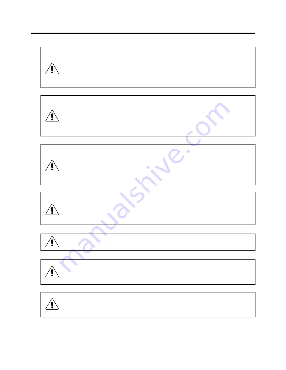
1-2. Safety notices
Warning
Before the computer is powered-on after part (FRU) replacement, make sure all screws, springs,
and other small parts are in place and are not left loose inside the computer. Verify this by
shaking the computer and listening for rattling sounds. Metallic parts or metal flakes can cause
electrical shorts.
Warning
some standby batteries contain a small amount of nickel and cadmium. Do not disassemble
a standby battery, recharge it, throw it into fire or water, or short-circuit it. Dispose of the battery
as required by local ordinances or regulations. Use only the battery in the appropriate parts
listing. Use of an incorrect battery can result in ignition or explosion of the battery
Warning
The battery pack contains small amounts of nickel. Do not disassemble it, throw it into fire or
water, or short-circuit it. Dispose of the battery pack as required by local ordinances or
regulations. Use only the battery in the appropriate parts listing when replacing the battery pack.
Use of an incorrect battery can result in ignition or explosion of the battery.
Warning
If the LCD breaks and the fluid from inside the LCD gets into your eyes or on your hands,
immediately was the affected areas with water for at least 15 minutes. Seek medical care if any
symptoms from the fluid are present after washing.
Warning
To avoid shock, do not remove the plastic cover that protects the lower part of the inverter card.
Warning
Though the main batteries have low voltage, a shorted or grounded battery can produce enough
current to burn personnel or combustible materials.
Warning
Before removing any part (FRU), turn off the computer, unplug all power cords from electrical
outlets, remove the battery pack, and then disconnect any interconnecting cables.
Ch1. Service information
Summary of Contents for F1
Page 1: ...0 Service Manual F1 LG Electronics ...
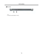
Page 15: ...14 Ch2 Locations Rear view 1 Fan 2 Security Key Hole Kensington Lock Hole ...
Page 56: ...55 Ch5 Removing and replacing a part ...
Page 58: ...57 3 Remove the Memory Module Ch5 Removing and replacing a part ...
Page 63: ...62 Ch5 Removing and replacing a part ...
Page 65: ...64 Ch5 Removing and replacing a part ...
Page 67: ...66 3 Remove the Keyboard Ch5 Removing and replacing a part ...
Page 69: ...68 3 Remove the Button Sub Board Ch5 Removing and replacing a part ...
Page 72: ...71 4 Remove the Display Module Ch5 Removing and replacing a part ...
Page 76: ...75 5 Remove the Main Board Ch5 Removing and replacing a part ...
Page 86: ...85 8 Disconnect the LCD Cable and the Inverter Connector Ch5 Removing and replacing a part ...
Page 92: ...91 NBATM NCVRB NCVRH NHDD1 NRUBS NSCR1 ...
Page 93: ...92 NODD1 NMEM1 NLAN1 NMDM1 NFAN1 ...
Page 94: ...93 NKBD1 NCPU1 NMCP1 NSPK1 NSPK1 NMLB1 NSUBU NSETR NCAPH NCABM NCAB3 NRUBR ...
Page 95: ...94 NCSEK NANTL NANTR NBRKR NSCR2 NCAB1 ...
Page 96: ...95 NSUBB NCSEB ...
Page 97: ...96 NBRKH NCSEF NHNGL NHNGR NSETR ...
Page 98: ...97 NSETF NCSER NLCD1 NNVE1 NCABN NCABL NPLTL ...
Page 99: ...98 NBRKL NBRKL NBRKL ...


