39
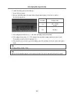
· If the voltage is not correct, replace the AC adapter.
· If the voltage is acceptable, do the following :
1. Replace the system board.
2. If the problem persists, check the AC adapter whether it is correct product or not.
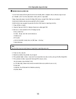
· Checking operational charging
1. To check whether the battery charges properly during operation, use a discharged battery pack or a
battery pack that has less than 50% of the total power remaining when installed in the computer.
Perform operational charging. If the battery status indicator or icon does not turn on, remove the battery
does not turn on, replace the battery pack.
2. If the charge indicator still does not turn on, replace the system board.
Then reinstall the battery pack.
Note
Noise from the AC adapter does not always indicate a defect.
Note
Do not charge battery pack, when its temperature is below 0 or above 75 .
· Checking the battery pack
1. Open the Power Meter window by clicking
Start
Control Panel
Power Options
and then;
check the total power remains. Battery charging does not start until the power Meter shows that less
than 95% of the total power remains; under this condition the battery pack can charge to 100% of its
capacity. This protects the battery pack from being overcharged or from having a shortened life.
2. To check the status of your batter, move your cursor to the Power Meter icon in the icon tray of the
Windows taskbar and wait for a moment (but do not click), and the percentage of battery power
remaining is displayed. To get detailed information about the battery, double-click the Power Meter icon.
Note
If the battery pack becomes hot, it may not be able to charge. Remove it from the computer and
Leave it at room temperature for a while. After it cools down, reinstall and recharge it.
Ch4. Symptom-to-part index
Summary of Contents for F1
Page 1: ...0 Service Manual F1 LG Electronics ...
Page 15: ...14 Ch2 Locations Rear view 1 Fan 2 Security Key Hole Kensington Lock Hole ...
Page 56: ...55 Ch5 Removing and replacing a part ...
Page 58: ...57 3 Remove the Memory Module Ch5 Removing and replacing a part ...
Page 63: ...62 Ch5 Removing and replacing a part ...
Page 65: ...64 Ch5 Removing and replacing a part ...
Page 67: ...66 3 Remove the Keyboard Ch5 Removing and replacing a part ...
Page 69: ...68 3 Remove the Button Sub Board Ch5 Removing and replacing a part ...
Page 72: ...71 4 Remove the Display Module Ch5 Removing and replacing a part ...
Page 76: ...75 5 Remove the Main Board Ch5 Removing and replacing a part ...
Page 86: ...85 8 Disconnect the LCD Cable and the Inverter Connector Ch5 Removing and replacing a part ...
Page 92: ...91 NBATM NCVRB NCVRH NHDD1 NRUBS NSCR1 ...
Page 93: ...92 NODD1 NMEM1 NLAN1 NMDM1 NFAN1 ...
Page 94: ...93 NKBD1 NCPU1 NMCP1 NSPK1 NSPK1 NMLB1 NSUBU NSETR NCAPH NCABM NCAB3 NRUBR ...
Page 95: ...94 NCSEK NANTL NANTR NBRKR NSCR2 NCAB1 ...
Page 96: ...95 NSUBB NCSEB ...
Page 97: ...96 NBRKH NCSEF NHNGL NHNGR NSETR ...
Page 98: ...97 NSETF NCSER NLCD1 NNVE1 NCABN NCABL NPLTL ...
Page 99: ...98 NBRKL NBRKL NBRKL ...

