background image

- 5 -

General Soldering Guidelines

1. Use a grounded-tip, low-wattage soldering iron and

appropriate tip size and shape that will maintain tip
temperature within the range or 500 F to 600 F.

2. Use an appropriate gauge of RMA resin-core solder

composed of 60 parts tin/40 parts lead.

3. Keep the soldering iron tip clean and well tinned.

4. Thoroughly clean the surfaces to be soldered. Use a

mall wire-bristle (0.5 inch, or 1.25cm) brush with a

metal handle.

Do not use freon-propelled spray-on cleaners.

5. Use the following unsoldering technique

a. Allow the soldering iron tip to reach normal

temperature.
(500 F to 600 F)

b. Heat the component lead until the solder melts.

c. Quickly draw the melted solder with an anti-static,

suction-type solder removal device or with solder

braid.

CAUTION: 

Work quickly to avoid overheating the

circuitboard printed foil.

6. Use the following soldering technique.

a. Allow the soldering iron tip to reach a normal

temperature (500 F to 600 F)

b. First, hold the soldering iron tip and solder the strand

against the component lead until the solder melts.

c. Quickly move the soldering iron tip to the junction of

the component lead and the printed circuit foil, and

hold it there only until the solder flows onto and

around both the component lead and the foil.

CAUTION:

Work quickly to avoid overheating the

circuit board printed foil.

d. Closely inspect the solder area and remove any

excess or splashed solder with a small wire-bristle

brush.

IC Remove/Replacement

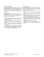
Some chassis circuit boards have slotted holes (oblong)

through which the IC leads are inserted and then bent flat

against the circuit foil. When holes are the slotted type,

the following technique should be used to remove and

replace the IC. When working with boards using the

familiar round hole, use the standard technique as

outlined in paragraphs 5 and 6 above.

Removal

1. Desolder and straighten each IC lead in one operation

by gently prying up on the lead with the soldering iron

tip as the solder melts.

2. Draw away the melted solder with an anti-static

suction-type solder removal device (or with solder

braid) before removing the IC.

Replacement

1. Carefully insert the replacement IC in the circuit board.

2. Carefully bend each IC lead against the circuit foil pad

and solder it.

3. Clean the soldered areas with a small wire-bristle

brush. (It is not necessary to reapply acrylic coating to

the areas).

"Small-Signal" Discrete Transistor
Removal/Replacement

1. Remove the defective transistor by clipping its leads as

close as possible to the component body.

2. Bend into a "U" shape the end of each of three leads

remaining on the circuit board.

3. Bend into a "U" shape the replacement transistor leads.

4. Connect the replacement transistor leads to the

corresponding leads extending from the circuit board

and crimp the "U" with long nose pliers to insure metal

to metal contact then solder each connection.

Power Output, Transistor Device
Removal/Replacement

1. Heat and remove all solder from around the transistor

leads.

2. Remove the heat sink mounting screw (if so equipped).

3. Carefully remove the transistor from the heat sink of the

circuit board.

4. Insert new transistor in the circuit board.

5. Solder each transistor lead, and clip off excess lead.

6. Replace heat sink.

Diode Removal/Replacement

1. Remove defective diode by clipping its leads as close

as possible to diode body.

2. Bend the two remaining leads perpendicular y to the

circuit board.

3. Observing diode polarity, wrap each lead of the new

diode around the corresponding lead on the circuit

board.

4. Securely crimp each connection and solder it.

5. Inspect (on the circuit board copper side) the solder

joints of the two "original" leads. If they are not shiny,

reheat them and if necessary, apply additional solder.

Fuse and Conventional Resistor
Removal/Replacement

1. Clip each fuse or resistor lead at top of the circuit board

hollow stake.

2. Securely crimp the leads of replacement component

around notch at stake top.

3. Solder the connections.

CAUTION:

Maintain original spacing between the

replaced component and adjacent components and the

circuit board to prevent excessive component

temperatures.

Copyright 
Only for training and service purposes

LGE Internal Use Only

2010 LG Electronics. Inc. All right reserved.

Summary of Contents for Flatron 27EA63V

Page 1: ...ebsite http biz LGservice com E mail http www LGEservice com techsup html CAUTION BEFORE SERVICING THE UNIT READ THE SAFETY PRECAUTIONS IN THIS MANUAL CHASSIS NO LM13E MODEL Same model for Service Internal Use Only 27EA63V 27EA63V B ...

Page 2: ...45 9 cm 18 07 8 WEIGHT with TILT SWIVEL Net Weight 4 8 kg 9 68 lbs Gross Weight 7 2 kg 15 87 lbs SPECIFICATIONS MODE POWER ON NORMAL STAND BY SUSPEND DPMS OFF POWER S W OFF H V SYNC ON ON OFF ON ON OFF OFF OFF POWER CONSUMPTION less than 41 W max less than 34 W typ LED COLOR OFF VIDEO ACTIVE OFF OFF OFF Copyright Only for training and service purposes LGE Internal Use Only RED BLINKING less than 0...

Page 3: ...cuit C MOS Make certain that treatment person s body are grounded through wrist band Do not leave the module in high temperature and in areas of high humidity for a long time The module not be exposed to the direct sunlight Avoid contact with water as it may a short circuit within the module If the surface of panel become dirty please wipe it off with a softmaterial Cleaning with a dirty or rough ...

Page 4: ...fore connecting the test receiver positive lead Always remove the test receiver ground lead last 9 Use with this receiver only the test fixtures specified in this service manual CAUTION Do not connect the test fixture ground strap to any heat sink in this receiver Electrostatically Sensitive ES Devices Some semiconductor solid state devices can be damaged easily by static electricity Such componen...

Page 5: ...h an anti static suction type solder removal device or with solder braid before removing the IC Replacement 1 Carefully insert the replacement IC in the circuit board 2 Carefully bend each IC lead against the circuit foil pad and solder it 3 Clean the soldered areas with a small wire bristle brush It is not necessary to reapply acrylic coating to the areas Small Signal Discrete Transistor Removal ...

Page 6: ...ut away copper pattern and let it overlap the previously scraped end of the good copper pattern Solder the overlapped area and clip off any excess jumper wire At Other Connections Use the following technique to repair the defective copper pattern at connections other than IC Pins This technique involves the installation of a jumper wire on the component side of the circuit board 1 Remove the defec...

Page 7: ...00 40 128 88 4 V Lines 40 0 60 317 628 600 1 4 23 800 x 600 H Pixels 46 875 1056 800 16 80 160 5 V Lines 49 5 75 0 625 600 1 3 21 800 x 600 H Pixels 48 363 1344 1024 24 136 160 6 V Lines 65 0 60 0 806 768 3 6 29 1024 x 768 H Pixels 60 023 1312 1024 16 96 176 7 V Lines 78 75 75 029 800 768 1 3 28 1024 x 768 H Pixels 67 500 1600 1152 64 128 256 8 V Lines 108 0 75 000 900 864 1 3 32 1152 x 864 H Pixe...

Page 8: ...MY KEY FUNCTION AUTO INPUT Exit 19V From Adapter 19 to 5V DC DC 5V to 3 3V LDO 5V to1 2V LDO LED B L T Con 5V System 3 3V Core 1 2V NT68773 Novatek RGB R G B H V 4M SERIAL Flash LED PANEL Blade5 F HD LVDS RGB IIC V_LED F B SPI Data CLK 24C02 DVI_TMDS DVI IIC H P HP L R out Key IIC LED RED DVI D 24C02 HDMI_TMDS HDMI IIC HDMI Embedded LED Driver Block ...

Page 9: ...eo signal converted analog to digital interpolates input to 1920X1080 resolution signal and outputs 8 bit R G B signal to transmitter 2 Power Part This part consists of a DC DC converter converting 19V that is powered by adapter to 5V and one regulators converting 5V to 3 3V and 1 2V 19V is also supplied to LED driver IC to power module and other converted powers supplies to IC components of main ...

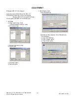
Page 10: ...serPort sys file to c WINNT system32 drivers folder b Run Userport exe c Remove all default number d Add 300 3FF e Click Start button f Click Exit button 2 EDID Read Write 1 Run WinEDID exe 2 Edit Week of Manufacture Year of Manufacture Serial Number a Input User Info Data b Click Update button c Click Write button Copyright Only for training and service purposes LGE Internal Use Only 2010 LG Elec...

Page 11: ...al 3 The SVC OSD menu contains additional menus that the User OSD menu as described below a CLEAR ETI To initialize using time c Auto Color W B balance and Automatically sets the gain and offset value press key for over 3 sec d AGING Select Aging mode on off b Module To select applied module d NVRAM INIT EEPROM initialize 24C16 press key for over 3 sec e R G B 9300K Allows you to set the R G B 930...

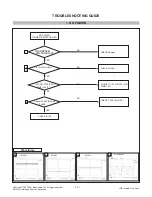
Page 12: ...C102 3 3 IC103 1 4 Copyright Only for training and service purposes LGE Internal Use Only 2010 LG Electronics Inc All right reserved IS ADAPTER VOLTAGE 19V IS IC102 PIN 3 5V IS IC 103 PIN1 3 3V PIN3 1 2V IC100 45 46 5V Check IC100 PIN 45 46 PULSE YES NO CHECK CRYSTAL X100 CHECK Adapter CHECK IC 103 PIN1 3 3 PIN CHECK IC102 5V PIN3 1 2V ...

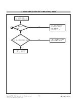
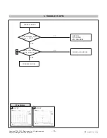
Page 13: ...ROUBLE IN IC100 NO NO CHECK IC100PIN 45 46 PULSE CHECK CONNECTION LINE FROM D SUB TO IC100 TROUBLE IN CABLE OR LCD MODULE YES NO RASTER OSD IS NOT DISPLAYED YES 1 Copyright Only for training and service purposes LGE Internal Use Only 2010 LG Electronics Inc All right reserved CHECK IC100 PIN 39 40 PULSE ...

Page 14: ...ING INTO DPM MODE NO CHECK H V SYNC LINE NO YES CHECK IC100 PIN 39 HSYNC PIN40 VSYNC YES 1 H SYNC 2 V SYNC Waveforms 1 2 Copyright Only for training and service purposes LGE Internal Use Only 2010 LG Electronics Inc All right reserved CHECK JK202 PIN13 H sync PIN 14 V sync ...

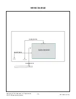
Page 15: ...WIRING DIAGRAM 16 Copyright Only for training and service purposes LGE Internal Use Only 2010 LG Electronics Inc All right reserved EAD62122554 EAD62186008 EAD38438705 ...

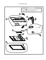
Page 16: ...300 510 520 530 420 400 430 900 200 540 410 or ...

Page 17: ...PDF created with pdfFactory Pro trial version www pdffactory com ...

Page 18: ...PDF created with pdfFactory Pro trial version www pdffactory com ...

Page 19: ...OCTOBER 2012 P NO Printed in China MFL59082084 ...

Reviews: