background image

- 5 -

Copyright © 2010 LG Electronics. Inc. All right reserved.
Only for training and service purposes

LGE Internal Use Only

IC Remove/Replacement

Some chassis circuit boards have slotted holes (oblong) through
which the IC leads are inserted and then bent flat against the
circuit foil. When holes are the slotted type, the following technique
should be used to remove and replace the IC. When working with
boards using the familiar round hole, use the standard technique
as outlined in paragraphs 5 and 6 above.

Removal

1.  Desolder and straighten each IC lead in one operation by gently

prying up on the lead with the soldering iron tip as the solder
melts.

2.  Draw away the melted solder with an anti-static suction-type

solder removal device (or with solder braid) before removing the
IC.

Replacement

1.  Carefully insert the replacement IC in the circuit board.
2.  Carefully bend each IC lead against the circuit foil pad and

solder it.

3.  Clean the soldered areas with a small wire-bristle brush.

(It is not necessary to reapply acrylic coating to the areas).

"Small-Signal" Discrete TransistorRemoval/Replacement

1.  Remove the defective transistor by clipping its leads as close as

possible to the component body.

2.  Bend into a "U" shape the end of each of three leads remaining

on the circuit board.

3.  Bend into a "U" shape the replacement transistor leads.
4.  Connect the replacement transistor leads to the corresponding

leads extending from the circuit board and crimp the "U" with
long nose pliers to insure metal to metal contact then solder
each connection.

Power Output, Transistor Device
Removal/Replacement

1.  Heat and remove all solder from around the transistor leads.
2. Remove the heat sink mounting screw (if so equipped).
3.  Carefully remove the transistor from the heat sink of the circuit

board.

4.  Insert new transistor in the circuit board.
5. Solder each transistor lead, and clip off excess lead.
6.  Replace heat sink.

Diode Removal/Replacement

1.  Remove defective diode by clipping its leads as close as

possible to diode body.

2.  Bend the two remaining leads perpendicular y to the circuit

board.

3.  Observing diode polarity, wrap each lead of the new diode

around the corresponding lead on the circuit board.

4.  Securely crimp each connection and solder it.
5. Inspect (on the circuit board copper side) the solder joints of

the two "original" leads. If they are not shiny, reheat them and if
necessary, apply additional solder.

Fuse and Conventional Resistor
Removal/Replacement

1.  Clip each fuse or resistor lead at top of the circuit board hollow

stake.

2.  Securely crimp the leads of replacement component around

notch at stake top.

3.  Solder the connections.

CAUTION:

Maintain original spacing between the replaced

component and adjacent components and the circuit board to
prevent excessive component temperatures.

Circuit Board Foil Repair

Excessive heat applied to the copper foil of any printed circuit
board will weaken the adhesive that bonds the foil to the circuit
board causing the foil to separate from or "lift-off" the board. The
following guidelines and procedures should be followed whenever
this condition is encountered.

At IC Connections

To repair a defective copper pattern at IC connections use the
following procedure to install a jumper wire on the copper pattern
side of the circuit board. (Use this technique only on IC
connections).

1.  Carefully remove the damaged copper pattern with a sharp

knife. (Remove only as much copper as absolutely necessary).

2. carefully scratch away the solder resist and acrylic coating (if

used) from the end of the remaining copper pattern.

3.  Bend a small "U" in one end of a small gauge jumper wire and

carefully crimp it around the IC pin. Solder the IC connection.

4. Route the jumper wire along the path of the out-away copper

pattern and let it overlap the previously scraped end of the good
copper pattern. Solder the overlapped area and clip off any
excess jumper wire.

At Other Connections

Use the following technique to repair the defective copper pattern
at connections other than IC Pins. This technique involves the
installation of a jumper wire on the component side of the circuit
board.

1.  Remove the defective copper pattern with a sharp knife.

Remove at least 1/4 inch of copper, to ensure that a hazardous
condition will not exist if the jumper wire opens.

2. Trace along the copper pattern from both sides of the pattern

break and locate the nearest component that is directly
connected to the affected copper pattern.

3. Connect insulated 20-gauge jumper wire from the lead of the

nearest component on one side of the pattern break to the lead
of the nearest component on the other side.
Carefully crimp and solder the connections.

CAUTION:

Be sure the insulated jumper wire is dressed so the

it does not touch components or sharp edges.

Summary of Contents for Flatron 27UD68P

Page 1: ...R SERVICE MANUAL North Latin America http aic lgservice com Europe Africa http eic lgservice com Asia Oceania http biz lgservice com CAUTION BEFORE SERVICING THE UNIT READ THE SAFETY PRECAUTIONS IN THIS MANUAL CHASSIS NO LM55H MODEL 27UD68P Internal Use Only ...

Page 2: ...right reserved Only for training and service purposes LGE Internal Use Only CONTENTS CONTENTS 2 PRECAUTION 3 SERVICING PRECAUTIONS 4 SPECIFICATIONS 6 TIMING CHART 11 ADJUSTMENT 14 BLOCK DIAGRAM 18 TROUBLE SHOOTING 19 EXPLODED VIEW 22 SVC SHEET ...

Page 3: ...he module from the ESD as it may damage the electronic circuit C MOS Make certain that treatment person s body are grounded through wrist band Do not leave the module in high temperature and in areas of high humidity for a long time The module not be exposed to the direct sunlight Avoid contact with water as it may a short circuit within the module If the surface of panel become dirty please wipe ...

Page 4: ...any electrostatic charge on your body by touching a known earth ground Alternatively obtain and wear a commercially available discharging wrist strap device which should be removed to prevent potential shock reasons prior to applying power to the unit under test 2 After removing an electrical assembly equipped with ES devices place the assembly on a conductive surface such as aluminum foil to prev...

Page 5: ...the solder joints of the two original leads If they are not shiny reheat them and if necessary apply additional solder Fuse and Conventional Resistor Removal Replacement 1 Clip each fuse or resistor lead at top of the circuit board hollow stake 2 Securely crimp the leads of replacement component around notch at stake top 3 Solder the connections CAUTION Maintain original spacing between the replac...

Page 6: ... 1 00 0 05 M Shape Wall out Color Black Weight 0 16kg Power cord can be changed according to region If wall mount adapter is applied Power cord doesn t apply to the BOM HDMI Length 1 5m Shape Detachable Type Color Black Weight 0 091kg SET accessory P N EAD00926125 CABLE 100Ω 10Ω CONNECTOR 100Ω 15Ω DisplayPort Length 1 8m Shape Detachable Type Color Black Weight 0 095kg SET accessory P N EAD6312760...

Page 7: ...roduct Weight Only SET 8 0kg 5 9kg With Stand Without Stand With BOX 10 8kg Only Stand Accessory 0 5 5 0 4 5 3 Container Loading Quantity Individual or Palletizing 20ft 40ft EA Indi Pallet Indi Pallet 200 200 600 440 4 Stand Assy Type Base detachable Size W x D x H 504 3 252 4 418 8 mm Tilt Degree 5 1 5 20 1 5 degree Tilt force 1 0 3 0 kgf Folding Degree N A Height length 120 2 mm 5 Appearance Gen...

Page 8: ...N 1000 TYP DFC Æ 1 000 000 1 min 5 000 000 1 Typ DFC test condition Full black pattern MSPG 126 timing DFC ON Picture Picture Adjust 4 Response Time TGTG Gray to Gray 14ms Typ 25ms Max 5 CIE Color Coordinates 색 좌표 Minimum Normal Maximum White WX Typ 0 03 0 313 Typ 0 03 Warm 6500K WY 0 329 White WX Typ 0 03 0 295 Typ 0 03 Medium 8000K WY 0 305 White WX Typ 0 03 0 283 Typ 0 03 Cool 9300K WY 0 298 6 ...

Page 9: ... Horizontal 30 135kHz Vertical 56 61 Hz Native 60Hz DP Horizontal 30 135kHz Vertical 56 61 Hz Native 60Hz PBP mode can t support FreeSync 3 Resolution Single HDMI Max 3840 2160 60Hz Recommend 3840 2160 60Hz DP Max 3840 2160 60Hz Recommend 3840 2160 60Hz PBP HDMI Max 1920 2160 60Hz Recommend 1920 2160 60Hz DP Max 1920 2160 60Hz Recommend 1920 2160 60Hz 4 Input Voltage Voltage 100 240 Vac 50 or 60Hz...

Page 10: ...surement condition 1 page 21 Adapter output 48W Adapter input Sleep Mode Off On On Off Off Off Off White Blinking 0 5W PC Stand by Mode Off Mode Off 0 3W DC Switch Off EPA On On Test video White 66 31W EPA6 0 test standard ERP On On Test video White 30 2W ERP A class Condition Outgoing condition Power rating 19V 2 0A SMART ENERGY SAVING On Off Efficiency low 15 5 high 25 5 Test with outgoing condi...

Page 11: ...1 100 Mute Input HDMI1 HDMI2 DP Ratio Wide Original 1 1 PBP SUB Off HDMI1 HDMI2 DP Sound out Main Audio Sub Audio Swap Sub Full Ratio Main Wide Original Sub Wide Original Picture Picture Mode Custom Reader Photo Cinema sRGB Color weakness FPS Game1 FPS Game 2 RTS Game Custom Game Picture Adjust Super Resolution High Middle Low Off Sharpness 0 100 Black Level High Low HDMI HD UHD Deep Color On Off ...

Page 12: ...0 Six Color Red Hue Saturation 0 100 Green Hue Saturation 0 100 Blue Hue Saturation 0 100 Cyan Hue Saturation 0 100 Magenta Hue Saturation 0 100 Yellow Hue Saturation 0 100 Reset Reset Cancel General Language English Germanic French Spanish Italian Swedish Finnish Portuguese Portuguese brazil Polish Russian Greek Ukrainian Chinese Japanese Korean Smart Energy Saving Off Low High FreeSync On Off Po...

Page 13: ...t 2010 LG Electronics Inc All right reserved Only for training and service purposes LGE Internal Use Only Reset Reset Cancel 5 2 Open Source License If Need Open Source Use Manual License in Web Source in Web O O O ...

Page 14: ...e LCD Monitor Should be within Cabinet s Bezel 2 Distance Difference between Active Area and Bezel A A B A B 1 0 mm C D 1 0 mm A The Distance from The Left of Active Area to the Bezel Bezel B The Distance from The Right of Active Area to the Bezel C The Distance from The Top of Active Area to the Bezel D The Distance from The Bottom of Active Area to the Bezel D 5 Applying module Character 1 LCD M...

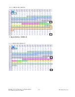
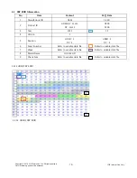
Page 15: ... 085B 2 Product ID DP 23305 095B 3 Year 2015 19 4 Version 1 HDMI 3 HDMI 3 5 Revision DP 4 DP 4 6 Serial Number Refer to variable data file Refer to variable data file 7 Week Refer to variable data file Refer to variable data file 8 Model Name LG Ultra HD 9 Check Sum Refer to variable data file Refer to variable data file 10 Special Item 6 1 1 1 HDMI1 EDID HDMI1 4 1 Physical Address HDMI1 10 ...

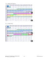
Page 16: ... 16 Copyright 2010 LG Electronics Inc All right reserved Only for training and service purposes LGE Internal Use Only 2 1 1 2 HDMI2 EDID HDMI1 4 1 Physical Address HDMI2 20 2 1 1 3 HDMI1 EDID HDMI2 0 ...

Page 17: ... 17 Copyright 2010 LG Electronics Inc All right reserved Only for training and service purposes LGE Internal Use Only 2 1 1 4 HDMI2 EDID HDMI2 0 2 1 2 DP EDID DP1 2 ...

Page 18: ... 18 Copyright 2010 LG Electronics Inc All right reserved Only for training and service purposes LGE Internal Use Only 2 1 3 DP EDID Of FREE SYNC ON ...

Page 19: ...SM 1E 6D 2 Product ID HDMI1 2 23304 DP 23305 085B 095B 3 Year 2015 19 4 Version 1 5 Revision HDMI 3 DP 4 HDMI 3 DP 4 6 Serial Number Refer to variable data file Refer to variable data file 7 Week Refer to variable data file Refer to variable data file 8 Model Name LG Ultra HD 9 Check Sum Refer to variable data file Refer to variable data file 2 2 1 1HDMI PBP EDID 2 2 1 2 HDMI2 PBP EDID ...

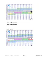
Page 20: ...0 Copyright 2010 LG Electronics Inc All right reserved Only for training and service purposes LGE Internal Use Only HDMI Physical address HDMI1 10 Æ CHECKSUM 3F HDMI2 20 Æ CHECKSUM 2F 2 2 1 3 DP PBP EDID ...

Page 21: ...347 1472 1152 32 96 192 1152 x 864 V Lines 60 05 905 864 1 3 37 5 H Pixels 74 250 45 00 1650 1280 110 40 220 1280 x 720 V Lines 60 00 750 720 5 5 20 6 H Pixels 108 63 981 1688 1280 48 112 248 1280 x 1024 V Lines 60 02 1066 1024 1 3 38 7 H Pixels 108 00 60 00 1800 1600 24 80 96 1600 x 900 V Lines 60 00 1000 900 1 3 96 8 H Pixels 148 5 67 5 2200 1920 88 44 148 1920 x 1080 V Lines 60 1125 1080 4 5 36...

Page 22: ...s 79 99 54 347 1472 1152 32 96 192 1152 x 864 V Lines 60 05 905 864 1 3 37 5 H Pixels 74 250 45 00 1650 1280 110 40 220 1280 x 720 V Lines 60 00 750 720 5 5 20 6 H Pixels 108 63 981 1688 1280 48 112 248 1280 x 1024 V Lines 60 02 1066 1024 1 3 38 7 H Pixels 108 00 60 00 1800 1600 24 80 96 1600 x 900 V Lines 60 00 1000 900 1 3 96 8 H Pixels 148 5 67 5 2200 1920 88 44 148 1920 x 1080 V Lines 60 1125 ...

Page 23: ...on Standard 2 5 Reserve after operation Above 5 Minutes Heat Run Temperature at 25 5 C Relative humidity 65 10 Input voltage 100 240V 50 60Hz 2 6 Adjustment equipments Color Analyzer CA 210 or CA 110 UA 10 DDC Adjustment Jig equipment 3 Main PCB check process APC After Manual Insult executing APC 3 1 ADC Process 27UD68 doesn t need ADC process because it has only digital input like DisplayPort and...

Page 24: ...n check the White balance according to below specification HDMI 1920x1080 Full White Tolerance 0 015 Luminance Spec min 250 Check condition custom mode out going condition Aging Time min x y 0 10 0 316 0 335 10 30 0 313 0 332 30 0 313 0 329 a Factory Calibration Gamma dE Color Temperature 6500k Reference Model 27MU67 Input HDMI1 2 Gray Pattern with Gamma correction using command using Adjustment C...

Page 25: ... 50 60Hz 1 Set Input to DisplayPort MiniDP HDMI1 HDMI2 2 Turn off the source device 3 Check DPM operation refer to the below table Operating Condition Sync H V or Video EUT MSPG6100 LED SET Wattage W Sleep mode Off Off Off White blinking 0 5W Off mode Off Mech Switch off Off 0 3W DC Switch Off 5 Shipping condition No Item Content Outgoing Condition 비고 2 Outgoing Condition SOURCE HDMI1 Power S W OF...

Page 26: ...vel Depends on video signal Low RGB limit YUV High RGB Full Black level enable at HDMI input UHD Deep Color Off DFC Off Response Time Middle Gamma 2 2 Color Temp Custom Manual 6500K Red 50 Green 50 Blue 50 Six Color Hue 50 Saturation 50 Language Depend on the sale region Super Energy Saving Low DAS Mode On Power LED Off Automatic Standby Europe 4H Others OFF DisplayPort 1 2 Enable OSD Lock Off Ope...

Page 27: ...ent contents CMD hex ADR VAL hex Explanation 1 EEPROM ALL INITIAL E4 00 00 adjustment Initialization 2 EEPROM READ E7 Slave add At EEPROM Read 3 EEPROM WRITE E8 Slave add Data Write data at EEPROM 4 R GAIN 16 00 00 64 Tune Gain 5 G GAIN 18 00 00 64 6 B GAIN 1A 00 00 64 7 BRIGHT Backlight 10 00 00 64 Tune Analog Bright 8 FACTORY RESET F0 00 00 Factory reset 9 AUTO_COLOR_ADJUST F1 00 0 AUTO COLOR Tu...

Page 28: ...MD E8h ADH E2 PROM Slave Address A0 A2 A4 A6 A8 AA AC AE Not 00h Reserved by Buffer To EEPROM ADL E2 PROM Sub Address 00 FF Data Write data Delay 20ms 6 5 2 Command Set No Adjustment contents CMD hex LEN Explanation 1 EEPROM WRITE E8 94 16 Byte Write 2 84 n n byte Write Use FOS Default write 14mode data write SyncFlags HPeriodH HPeriodL VtotalH VtotalL SrcHTotalH SrcHTotalL SrcHStartH SrcHStartL S...

Page 29: ... 80 FF Read 7 A6 0 3 Page 0 7F Read 8 80 3 Page 80 FF Read 9 A8 0 4 Page 0 7F Read 10 80 4 Page 80 FF Read 11 AA 0 5 Page 0 7F Read 12 80 5 Page 80 FF Read 13 AC 0 6 Page 0 7F Read 14 80 6 Page 80 FF Read 15 AE 0 7 Page 0 7F Read 16 80 7 Page 80 FF Read 6 6 3 Use Read E2 PROM s specific area as unit of 128 80h byte 84h 6 6 4 EDID Write EEPROM access by using DDC2B protocol 1 Byte write L 0x00 0x7F...

Page 30: ...Electronics Inc All right reserved Only for training and service purposes LGE Internal Use Only 6 6 5 EDID Read DDC2B Command A0 A1 128 Byte transfer of EDID Buffer of MICOM STOP A 00 A0 START A A CS A Data1 A1 START Data128 ...

Page 31: ...BLOCK DIAGRAM Main 31 Copyright 2010 LG Electronics Inc All right reserved Only for training and service purposes LGE Internal Use Only ...

Page 32: ...training and service purposes LGE Internal Use Only 1 NO POWER No power issue Check JK400 PIN 4 Is IC401 PIN2 19V PIN 3 5V CHECK ADAPTER CHECK IC401 Is IC 400 PIN2 3 3V CHECK IC400 Is IC200 PIN95 PIN96 PULSE CHECK CRYSTAL X200 YES YES YES NO NO NO NO CHECK IC200 IC401 2 IC401 3 IC400 X200 ...

Page 33: ...ses LGE Internal Use Only 2 NO RASTER OSD IS NOT DISPLAYED MAIN No Raster OSD is not displayed Check P201 PIN1 10V IC200 PIN95 96 12MHz CHECK IC402 PIN3 10V 1 CHECK 200 2 Trouble in IC200 Is IC200 PIN3 PIN4 I2C YES YES NO NO NO Trouble in cable or LCD module CHECK CONNECTION From HDMI TO IC200 ...

Page 34: ...reserved Only for training and service purposes LGE Internal Use Only 3 Trouble in DPM CHECK Signal cable connection Trouble in DPM Check Signal cable DET pin CHECK PC PC is going to the DPM mode YES YES NO NO Trouble in IC200 Check the Signal input ...

Page 35: ...ted characteristics These parts are identified by in the Schematic Diagram and EXPLODED VIEW It is essential that these special safety parts should be replaced with the same components as recommended in this manual to prevent X RADIATION Shock Fire or other Hazards Do not modify the original design without permission of manufacturer IMPORTANT SAFETY NOTICE 910 900 400 300 200 700 520 510 540 930 3...

Page 36: ... 24K 1 R132 2K 1 OPT R155 100K C340 4700pF 50V OPT R138 100K R152 1 5K C124 0 47uF 16V R130 4 7K 1 WLED_ADIM R147 39K A_DIM JP106 R136 100 C331 4 7uF 25V IC102 DT1643S 3 EN 2 VREF1 4 PDIM 1 VIN 6 LS1 5 RISET 7 LS2 8 LGND 9 LS3 10 LS4 11 OVP 12 RT 13 COMP 14 CS 15 NDRV 16 VREF2 17 EP GND JP104 JP107 JP108 C125 1uF 50V C333 4 7uF 25V C343 33uF 100V WLED_ENABLE C344 33uF 100V R120 10K OPT R133 1K JP1...

Page 37: ...X1_0N 242 RX1_0P 243 RX1_1N 244 RX1_1P 245 RX1_2N 246 RX1_2P 247 GND_23 248 AVDD_RX 249 RX0_CN 250 RX0_CP 251 RX0_0N 252 RX0_0P 253 RX0_1N 254 RX0_1P 255 RX0_2N 256 RX0_2P 257 EP 1 15V_VDD C259 15pF 50V SDI C260 15pF 50V SDO R251 4 7K HDMI_SELECTION AVDD_AUDIO AVDD_RX SCK HDMI_5V SCK IC202 MX25L8006EM2I 12G 3 WP 2 SO SIO1 4 GND 1 CS 5 SI SIO0 6 SCLK 7 HOLD 8 VCC R221 4 7K EDP0 C266 0 1uF 16V HDMI1...

Page 38: ...C193 0 1uF 16V C185 0 1uF 16V OPT AVDDL_HRX0 C231 0 1uF 16V C214 10uF 10V OPT C234 0 1uF 16V VDDP C208 0 1uF 16V L107 BLM18PG121SN1D C242 0 1uF 16V L111 BLM18PG121SN1D 3 3V_NORMAL C220 10uF 10V VDDIO_A C115 10uF 10V C139 0 1uF 16V L117 BLM18PG121SN1D C251 0 1uF 16V OPT AVDD_PLL L121 BLM18PG121SN1D L113 BLM18PG121SN1D AVDDL_MOD C120 10uF 10V C222 10uF 10V C224 10uF 10V OPT C175 10uF 10V C249 0 1uF ...

Page 39: ...R409 10K OPT R422 10K 1 R414 51K 5V_STANDBY C439 4 7uF 25V OPT IC401 MP2315GJ 3 SW 2 IN 4 GND 1 AAM 5 BST 6 EN SYNC 7 VCC 8 FB C441 0 1uF 50V C442 0 1uF 50V R435 47K R440 51K 5V_ST_ON 19V C443 0 1uF 16V R436 100 5V_STANDBY R439 100 C440 4 7uF 25V 19V L401 C400 4 7uF 25V L400 OPT R402 100K R437 100K OPT R438 15K OPT C447 10uF 10V C448 10uF 10V C446 0 1uF 16V ZD405 5 6V OPT R441 75K 1 R442 14K 1 C41...

Page 40: ......

Reviews: