


- 8 -
(a)
(a)
(a)
(a)
(a)
(a)
(a)
(a)
(a)
(a)
(a)
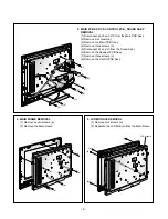
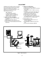
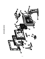
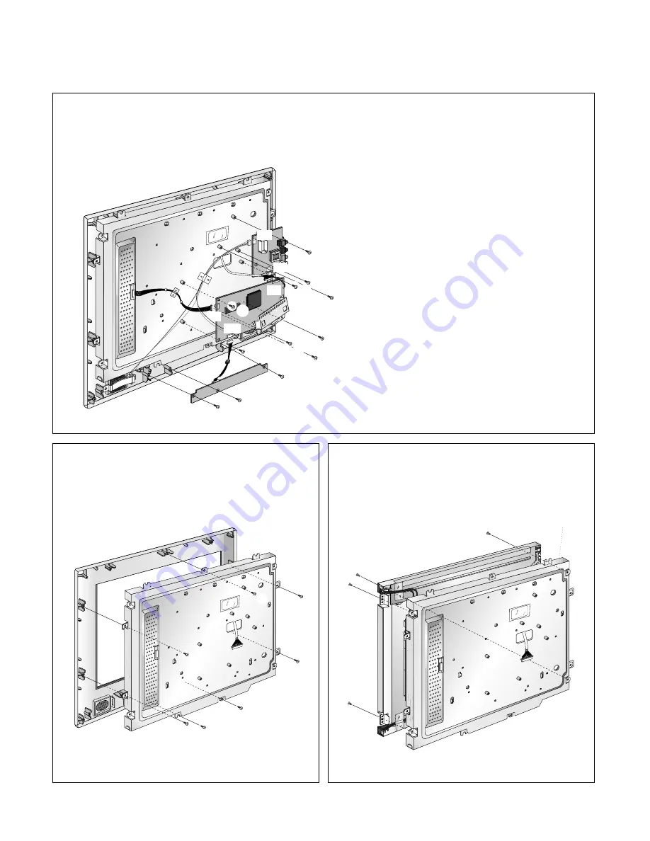
4. MAIN FRAME REMOVAL
(1) Remove seven screws (a).
(2) Remove the Main Frame.
5. LCD MODULE REMOVAL
(1) Remove four screws (a).
(2) Separate the LCD Module from the Main Frame.
LCD Module
(b)
(a)
(a)
(a)
(a)
(a)
(b)
(c)
(c)
(c)
(b)
(a)
J4
J3
J5
J4
J10
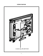
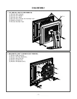
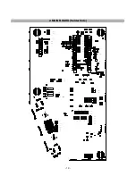
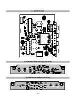
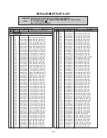
3. MAIN PCB ASS’Y & CONTROL PCB , SOUND ASS’Y
REMOVAL
(1) Disconnect J4,J5 and J10 from the Main PCB Ass’y.
(2) Remove six screws (a).
(3) Remove the Main PCB Ass’y.
(4) Remove three screws (b).
(5) Disconnect J4 and J3 from the Sound Ass’y
(6) Remove the Speaker PCB Ass’y.
(7) Remove three screws (c).
(8) Remove the Control PCB Ass’y.
Summary of Contents for FLATRON 568LM LM568E-CA
Page 6: ... 6 WIRING DIAGRAM J3 J4 CN5 CN4 CN2 CN3 CN1 J5 J4 J10 Connector Ass y P N 6631T11012N ...
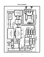
Page 31: ...SCHEMATIC DIAGRAM 31 1 GMZAN1 ...
Page 32: ... 32 2 LVDS ...
Page 33: ... 33 3 MICOM ...
Page 34: ... 34 4 POWER ...
Page 35: ... 35 5 CONNECTOR JACKS ...
Page 36: ... 36 6 AUDIO ...
Page 37: ... 37 7 CONTROL KEY ...


