


-14-
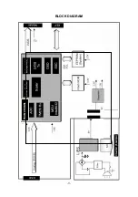
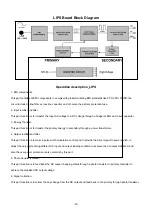
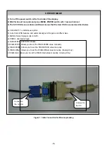
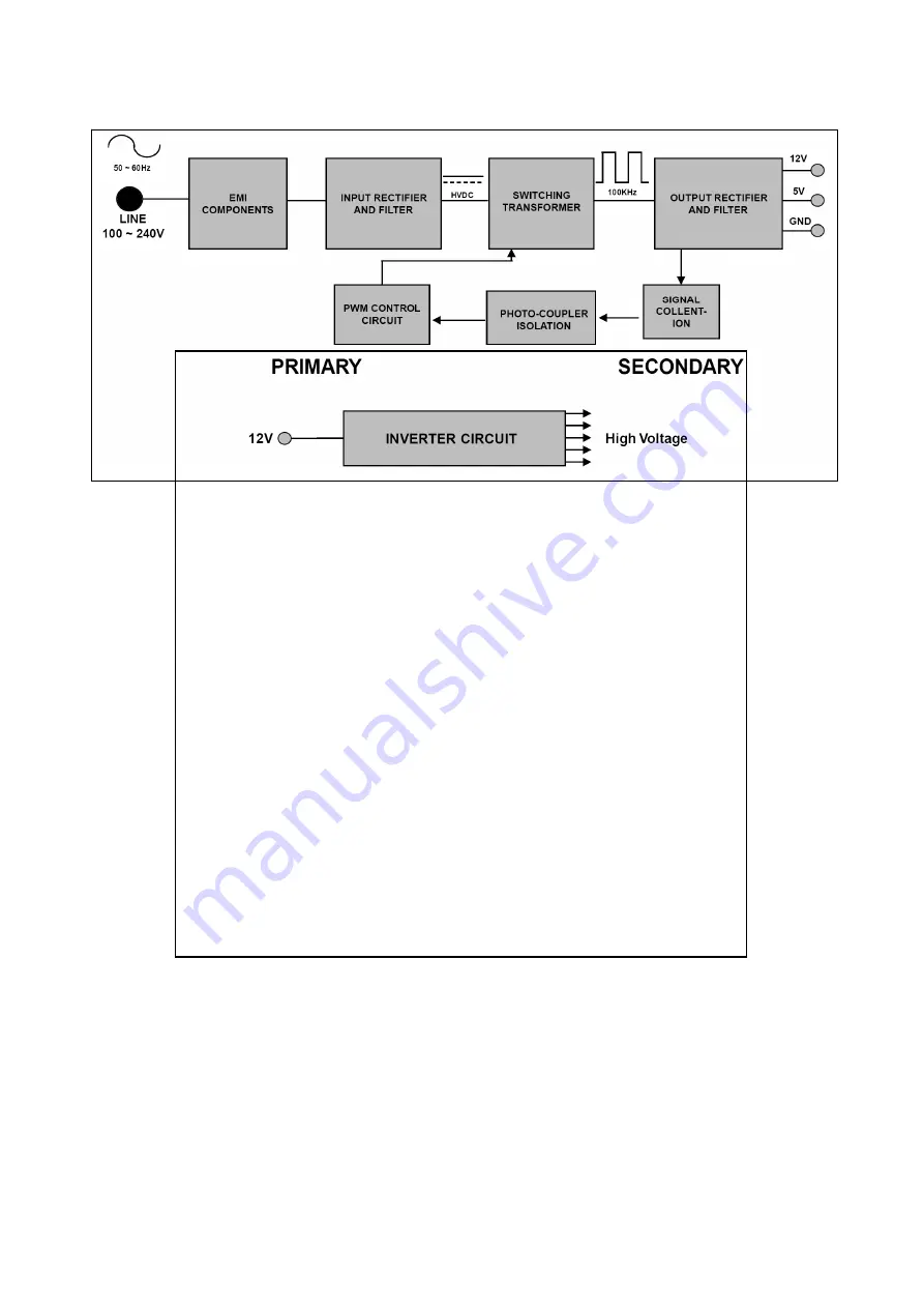
LIPS Board Block Diagram
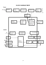
1. EMI components.
circuit included a line-filter, across line capacitor and of course the primary protection fuse.
2. Input rectifier and filter.
This part function is for transfer the primary energy to secondary through a power transformer.
4. Output rectifier and filter.
adjust the duty cycle during different AC input and output loading condition to achieve the dc output stabilized, and
also the over power protection is also monitor by this part.
5. Photo-Coupler isolation.
This part function is to feed back the DC output changing status through a photo transistor to primary controller to
achieve the stabilized DC output voltage.
6. Signal collection.
This part function is to collect the any change from the DC output and feed back to the primary through photo transistor.
Summary of Contents for Flatron L222WS
Page 11: ... 11 BLOCK DIAGRAM TSUMU18BWL h t t p w w w w j e l n e t ...
Page 23: ... 23 WIRING DIAGRAM 089G179E30H 20 095G8014 6D 46 095G 825 7D502 h t t p w w w w j e l n e t ...
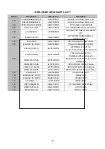
Page 24: ... 24 EXPLODED VIEW h t t p w w w w j e l n e t ...
Page 41: ...Jul 2007 P NO Printed in China h t t p w w w w j e l n e t ...


