background image

WARNING FOR THE SAFETY-RELATED COMPONENT.

• There are some special components used in LCD

monitor that are important for safety. 

These parts are

marked   on the schematic diagram and the
replacement parts list.

It is essential that these critical

parts should be replaced with the manufacturer’s

specified parts to prevent electric shock, fire or other

hazard.

• Do not modify original design without obtaining written

permission from manufacturer or you will void the

original parts and labor guarantee.

TAKE CARE DURING HANDLING THE LCD MODULE

WITH BACKLIGHT UNIT.

• Must mount the module using mounting holes arranged

in four corners.

• Do not press on the panel, edge of the frame strongly

or electric shock as this will result in damage to the

screen.

• Do not scratch or press on the panel with any sharp

objects, such as pencil or pen as this may result in

damage to the panel.

• Protect the module from the ESD as it may damage the

electronic circuit (C-MOS).

• Make certain that treatment person’s body are

grounded through wrist band.

• Do not leave the module in high temperature and in

areas of high humidity for a long time.

• The module not be exposed to the direct sunlight.
• Avoid contact with water as it may a short circuit within

the module.

• If the surface of panel become dirty, please wipe it off

with a softmaterial. (Cleaning with a dirty or rough cloth

may damage the panel.)

WARNING

BE CAREFUL ELECTRIC SHOCK ! 
• If you want to replace with the new backlight (CCFL) or

inverter circuit, must disconnect the AC adapter

because high voltage appears at inverter circuit about

650Vrms.

• Handle with care wires or connectors of the inverter

circuit. If the wires are pressed cause short and may

burn or take fire.

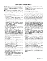
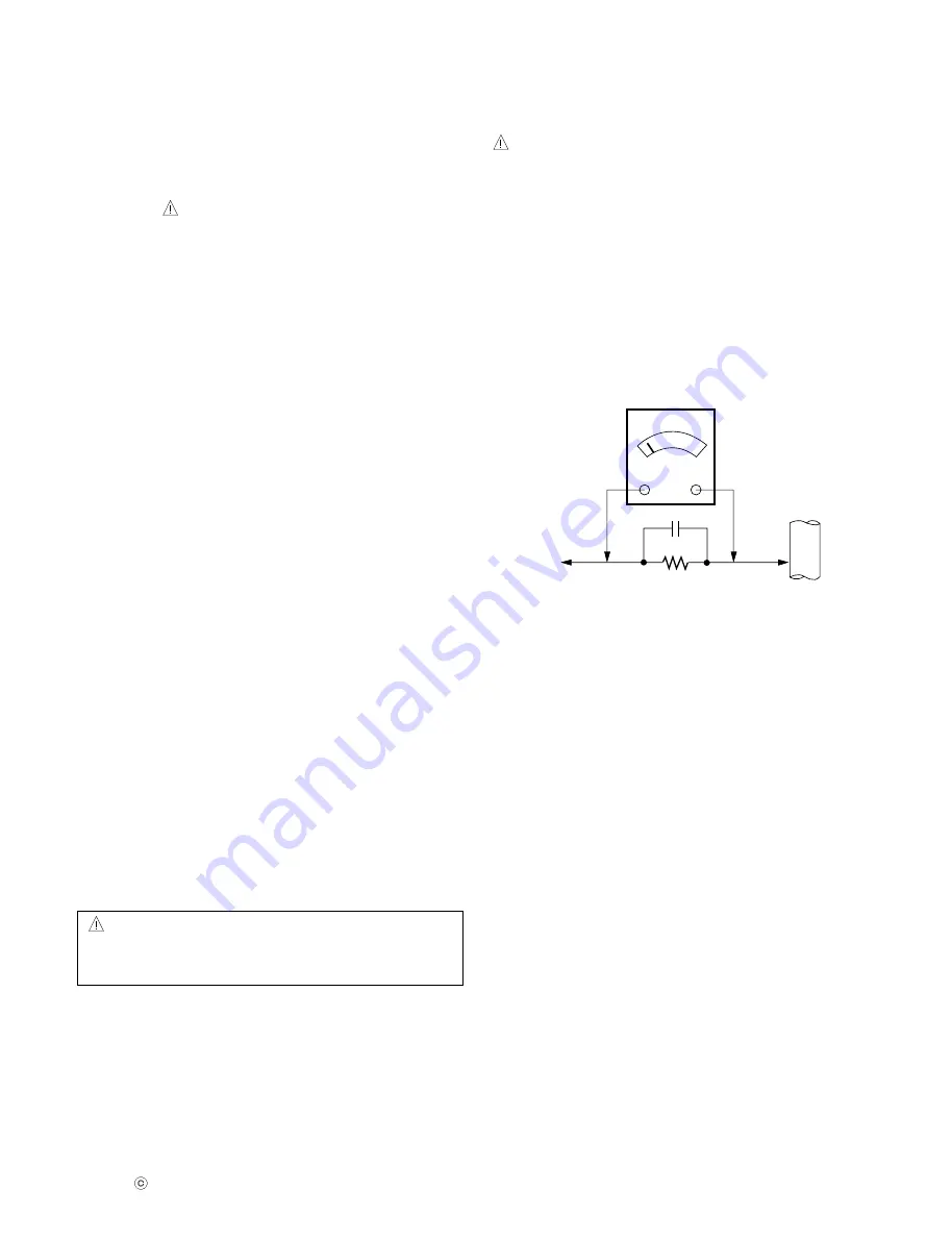
Leakage Current Hot Check Circuit

PRECAUTION

CAUTION

Please use only a plastic screwdriver to protect yourself
from shock hazard during service operation.

1.5 Kohm/10W

To Instrument's

exposed 

METALLIC PARTS

Good Earth Ground

such as WATER PIPE,

CONDUIT etc.

AC Volt-meter

Copyright 

2007 LG Electronics. Inc. All right reserved.

Only for training and service purposes

LGE Internal Use Only

3

-

Summary of Contents for FLATRON W2241S

Page 1: ...iz LGservice com E mail http www LGEservice com techsup html CAUTION BEFORE SERVICING THE UNIT READ THE SAFETY PRECAUTIONS IN THIS MANUAL CHASSIS NO LM73A MODEL W2241S W2241S BFT A P Same model for Service Internal Use Only W2241S W2241S PFT A P ...

Page 2: ... 1 Sync Signal Type Separate Sync SOG 3 2 Video Input Signal 1 Type R G B Analog 2 Voltage Level 0 0 7 V 3 Input Impedance 75 Ω 3 3 Operating Frequency Horizontal 30 83kHz Vertical 56 75Hz 4 MAX RESOLUTION Analog 1680 x 1050 60Hz 5 POWER SUPPLY 5 1 Power Adaptor Built in Power Input AC 100 240V 50 60Hz 1 0A 5 2 Power Consumption 6 ENVIRONMENT 6 1 Operating Temperature 10 C 35 C 50 F 95 F 6 2 Relat...

Page 3: ...it C MOS Make certain that treatment person s body are grounded through wrist band Do not leave the module in high temperature and in areas of high humidity for a long time The module not be exposed to the direct sunlight Avoid contact with water as it may a short circuit within the module If the surface of panel become dirty please wipe it off with a softmaterial Cleaning with a dirty or rough cl...

Page 4: ...e connecting the test receiver positive lead Always remove the test receiver ground lead last 9 Use with this receiver only the test fixtures specified in this service manual CAUTION Do not connect the test fixture ground strap to any heat sink in this receiver Electrostatically Sensitive ES Devices Some semiconductor solid state devices can be damaged easily by static electricity Such components ...

Page 5: ...n anti static suction type solder removal device or with solder braid before removing the IC Replacement 1 Carefully insert the replacement IC in the circuit board 2 Carefully bend each IC lead against the circuit foil pad and solder it 3 Clean the soldered areas with a small wire bristle brush It is not necessary to reapply acrylic coating to the areas Small Signal Discrete Transistor Removal Rep...

Page 6: ...away copper pattern and let it overlap the previously scraped end of the good copper pattern Solder the overlapped area and clip off any excess jumper wire At Other Connections Use the following technique to repair the defective copper pattern at connections other than IC Pins This technique involves the installation of a jumper wire on the component side of the circuit board 1 Remove the defectiv...

Page 7: ...2 1024 16 96 176 1024 x 768 V Lines 75 029 800 768 1 3 28 8 H Pixels 108 0 67 500 1600 1152 64 128 256 1152 x 864 V Lines 75 000 900 864 1 3 32 9 H Pixels 108 0 63 981 1688 1280 48 112 248 1280 x 1024 V Lines 60 02 1066 1024 1 3 38 10 H Pixels 135 0 79 976 1688 1280 16 144 248 1280 x 1024 V Lines 75 035 1066 1024 1 3 38 11 H Pixels 119 64 674 1840 1680 48 32 80 1680 x 1050 V Lines 59 883 1080 1050...

Page 8: ...e latch first Pull the cabinet upwards Then separate all latches on each side Remove the control button from cabinet Then disassemble the connector 1 4 Turn around the base lock to open the lock between base cover and stand body 6 2 3 5 Then separate stand body and base cover 7 8 Copyright 2007 LG Electronics Inc All right reserved Only for training and service purposes LGE Internal Use Only ...

Page 9: ...ROM System EEPROM System 3 3V 1680X1050 60Hz 146Mhz Dual Interface Engine Display Processing Engine Response Time Enhancement LVDS Panel Interface OSD Clock Generator MCU DRAM TSUMU58BWHL Flash ROM Flash ROM 3 3V Crystal Crystal 14 318MHz 9 1 8V EEPROM System Copyright 2007 LG Electronics Inc All right reserved Only for training and service purposes LGE Internal Use Only ...

Page 10: ...nalog to digital interpolates input to 1680 X 1050 resolution signal and outputs 8 bit R G B signal to transmitter 2 Power Part This part consists of the one 3 3V and one 1 8V regulators to convert power which is provided 5V in Power board 22V is provided for inverter 5V is provided for LCD panel and micom in W2241S case Also 5V is converted 3 3V and 1 8V by regulator Converted power is provided f...

Page 11: ...or transfer the input AC voltage to a DC voltage through a bridge rectifier and a bulk capacitor 3 Energy Transfer This part function is for transfer the primary energy to secondary through a power transformer 4 Output rectifier and filter This part function is to make a pulse width modulation control and to provide the driver signal to power switch to adjust the duty cycle during different AC inp...

Page 12: ...eed setup Windows 2000 XP Need to Port Setup This program is available for LCD Monitor only 1 Port Setup a Copy UserPort sys file to c WINNT system32 drivers folder b Run Userport exe c Remove all default number d Add 300 3FF e Click Start button f Click Exit button 2 EDID Read Write 1 Run WinEDID exe 2 Edit Week of Manufacture Year of Manufacture Serial Number a Input User Info Data b Click Updat...

Page 13: ...switch at the right side of the display 2 Wait for about 5 seconds and press MENU POWER switch for 1 second interval 3 The SVC OSD menu contains additional menus that the User OSD menu as described below a CLEAR ETI To initialize using time c Auto Color W B balance and Automatically sets the gain and offset value press key for over 3 sec d AGING Select Aging mode on off b Module To select applied ...

Page 14: ...OWER LINE CHECK U602 1 8V U601 3 3V LINE NO CHECK CRYSTAL X501 YES YES YES CHECK J703 VOLTAGE PIN5 PIN6 5V IS U602 PIN3 3 8V U601 PIN3 3 3V CHECK U501 PIN108 PULSE 1 2 1 3 1 4 Waveforms 1 J703 5 6 2 U602 2 3 U601 2 4 U501 108 14 Copyright 2007 LG Electronics Inc All right reserved Only for training and service purposes LGE Internal Use Only ...

Page 15: ...O NO 1 CONFIRM BRIGHTNESS OSD CONTRL STATUS 2 CHECK MICOM DIM ADJ PORT CHECK J703 PIN10 POWER BOARD LIPS CHECK PULSE AS CONTACTING PROBE TO THE LAMP WIRE OF THE LCD MODULE REPLACE LCD MODULE YES 1 2 3 YES YES YES Waveforms 1 J703 5 6 2 J703 10 3 LAMP CURRENT 15 Copyright 2007 LG Electronics Inc All right reserved Only for training and service purposes LGE Internal Use Only ...

Page 16: ...V U601 3 3V U501 PIN 108 109 14 3MHZ CHECK CONNECTION LINE FROM D SUB TO U501 TROUBLE IN CABLE OR LCD MODULE YES YES NO RASTER OSD IS NOT DISPLAYED CHECK U501 PIN27 H SYNC AND PIN28 V SYNC IS PULSE APPEARED AT SIGNAL PINS YES 1 Waveforms 4 U501 108 Copyright 2007 LG Electronics Inc All right reserved Only for training and service purposes LGE Internal Use Only 16 ...

Page 17: ...OING INTO DPM MODE NO CHECK H V SYNC LINE NO YES CHECK R730 AND R731 SYNC APPEARED CHECK U501 PIN27 28 SYNC PULSE YES 1 H SYNC 2 V SYNC Waveforms 1 2 Copyright 2007 LG Electronics Inc All right reserved Only for training and service purposes LGE Internal Use Only 17 ...

Page 18: ...WIRING DIAGRAM EAD37414503 EAD42157802 66631900030H 30P 6P 11P Copyright 2007 LG Electronics Inc All right reserved Only for training and service purposes LGE Internal Use Only 18 ...

Page 19: ...EXPLODED VIEW 300 320 310 410 400 430 910 920 440 200 330 450 460 19 420 ...

Page 20: ...slucent ABS power button lens 400 ACQ35578403 410 MDQ40929502 420 ADV36850101 430 MCK40926801 Cover MOLD ABS HF 350 Wx42 ABS Hinge body 440 MCK40927901 Cover MOLD ABS HF 350 Wx42 ABS HINGE COVER 910 MCK40928201 Cover MOLD ABS HF 350 Wx42 ABS Stand body 920 AAN35581101 Base Assembly BASE W2242 AB W2242 BASE ASM 200 EAJ38032801 LCD Module TFT CLAA220WA01ZBDWSXGA22 0INCH1680X1050300CDCOLOR72 16 10100...

Page 21: ......

Page 22: ......

Page 23: ......

Page 24: ......

Page 25: ...MAY 2008 P NO MFL32179265 Printed in China ...

Reviews: