


Chapter 3 Installation and wiring
3 - 2
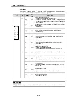
3.2 Wiring
3.2.1 Wiring precautions
①
Separate AC and external input signal of A/D module wiring not to be affected by
surge or induced noise in the AC.
②
External wiring has to be at least AWG32 (0.3mm
2
), and be selected in consideration
of operating ambiance and/or allowable current.
③
Separate wiring from device and/or substances generating intense heat, and oil not to
make short-circuit which leads to damage and/or mis -operation.
④
Be careful not to connect external power supply with wrong polarity.
⑤
Separate external wiring sufficiently from high voltage and power supply cable not to
cause induced noise or malfunction of module.
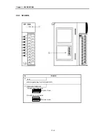
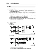
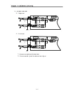
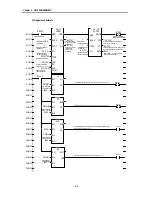
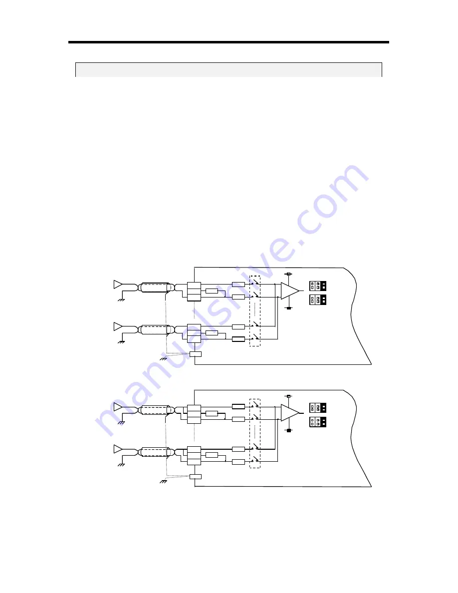
3.2.2 Wiring examples
1) G6F-AD2A
①
Voltage input
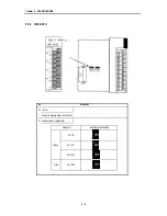
②
Current input
*1: Use a two-core twisted pair shielded cable
*2 : If noise is expected, ground the cable and FG terminal as shown in figure.
R
-15V
+15V
1 2 3
J1
J2
FG
G6F-AD2A
Input Range
Selection Switch
V+
I+
COM
R
R
R
R
R
V+
I+
COM
R
-15V
+15V
1 2 3
J1
J2
FG
G6F-AD2A
Input Range
Selection Switch
V+
I+
COM
R
R
R
R
R
V+
I+
COM
*1
*1
*1
*1
*2
*2


