- 21 -
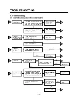
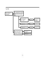
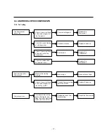
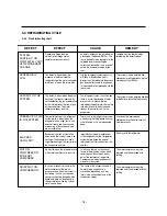
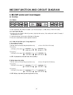
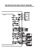
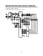
6. MICOM Function and Circuit diagram
6-1. Functions
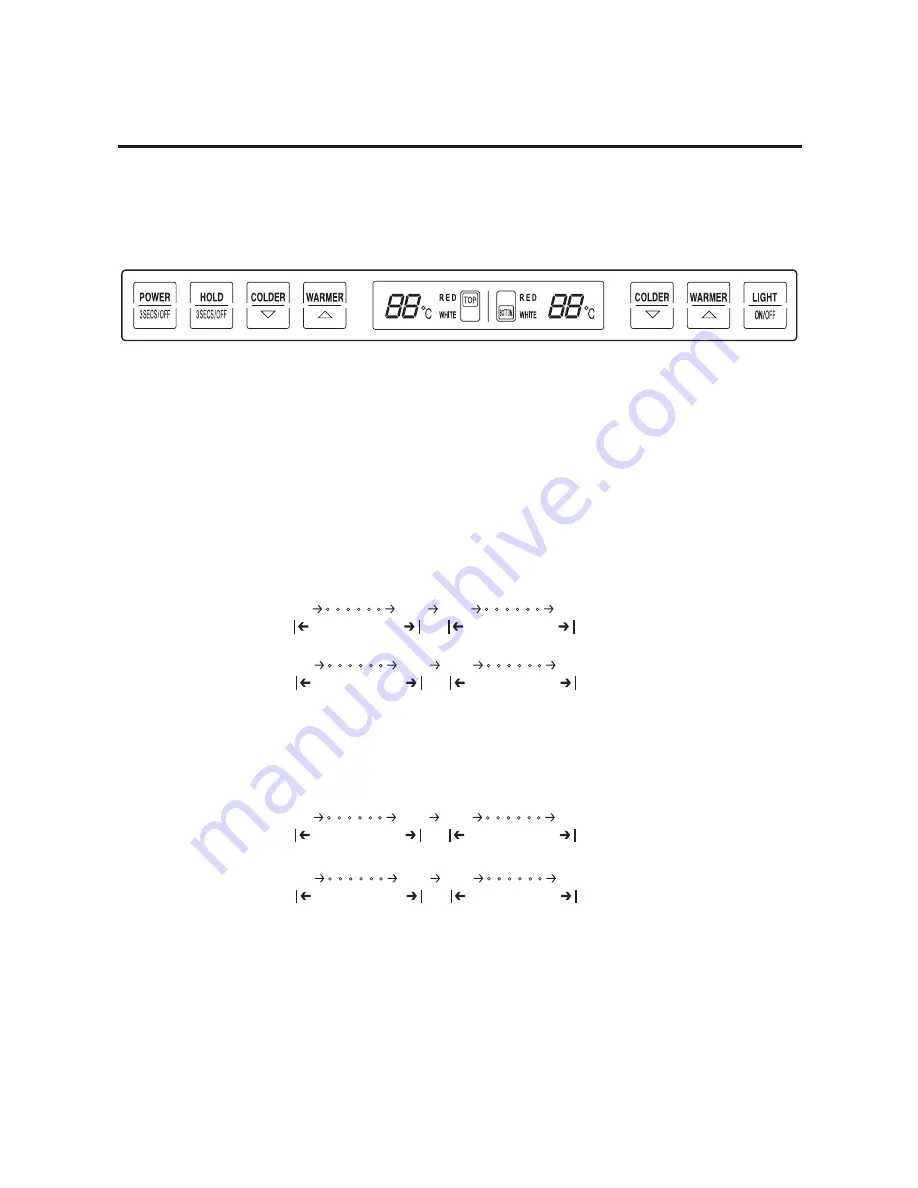
6-1-1. Displays
1. At the first power-up, the machine is unlocked. And, the initial setting is 14°C/RED for top, 8°C/WHITE for bottom.
6-1-2. Lock/Unlock Function
1. By pressing the ‘Lock/Unlock’ button for 3 seconds, it will unlock the machine. If the control panel is idle for 10 second, it
will automatically lock itself.
2. 1 minute after the lock, the luminosity of the display will decrease.
3. You have to cancel the lock in order to operate the machine.
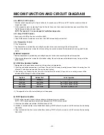
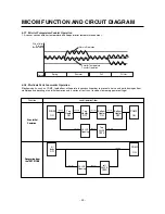
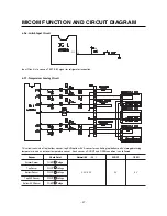
6-1-3. Setting the top/bottom parts’ storage temperature
(1) Top temperature setting
1. With the lock off, set the top storage temperature using ‘
’, ‘
’ button on the left side of the display.
2. By pressing ‘
’
It will display in the order of
3. By pressing ‘
’
It will display in the order of
4. NOTE: Top temperature cannot be lower than the bottom
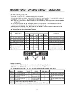
(2) Bottom temperature setting
1. With the lock off, set the top storage temperature using ‘
’, ‘
’ button on the right side of the display.
2. By pressing ‘
’
It will display in the order of
3. By pressing ‘
’
It will display in the order of
4. NOTE: Bottom temperature cannot be higher than the top.
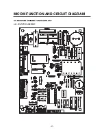
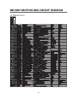
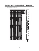
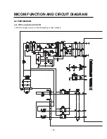
MICOM FUNCTION AND CIRCUIT DIAGRAM
WHITE LED ON
RED LED ON
6
°
C 11
°
C 12
°
C 18
°
C
RED LED ON
WHITE LED ON
18
°
C 12
°
C 11
°
C 6
°
C
WHITE LED ON
RED LED ON
6
°
C 11
°
C 12
°
C 18
°
C
RED LED ON
WHITE LED ON
18
°
C 12
°
C 11
°
C 6
°
C
Summary of Contents for GC-W061 series
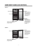
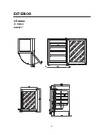
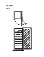
Page 8: ... 8 3 Exterior 3 1 Exterior GC W061 EXTERIOR ...
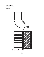
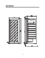
Page 9: ...GC W101 EXTERIOR 9 ...
Page 10: ...EXTERIOR 10 ...
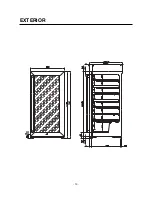
Page 11: ...GC W141 EXTERIOR 11 ...
Page 12: ...EXTERIOR 12 ...
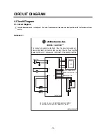
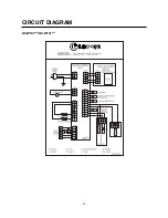
Page 14: ...CIRCUIT DIAGRAM 14 GC W101 GC W141 ...
Page 32: ...6 4 2 Replacement Parts List MICOM FUNCTION AND CIRCUIT DIAGRAM 32 ...
Page 33: ...6 4 3 PWB ASS Y DISPLAY AND PARTS LIST MICOM FUNCTION AND CIRCUIT DIAGRAM 33 ...
Page 35: ...MICOM FUNCTION AND CIRCUIT DIAGRAM 35 ...