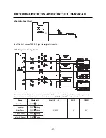
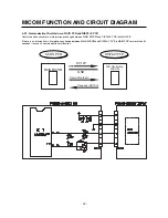
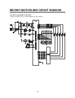

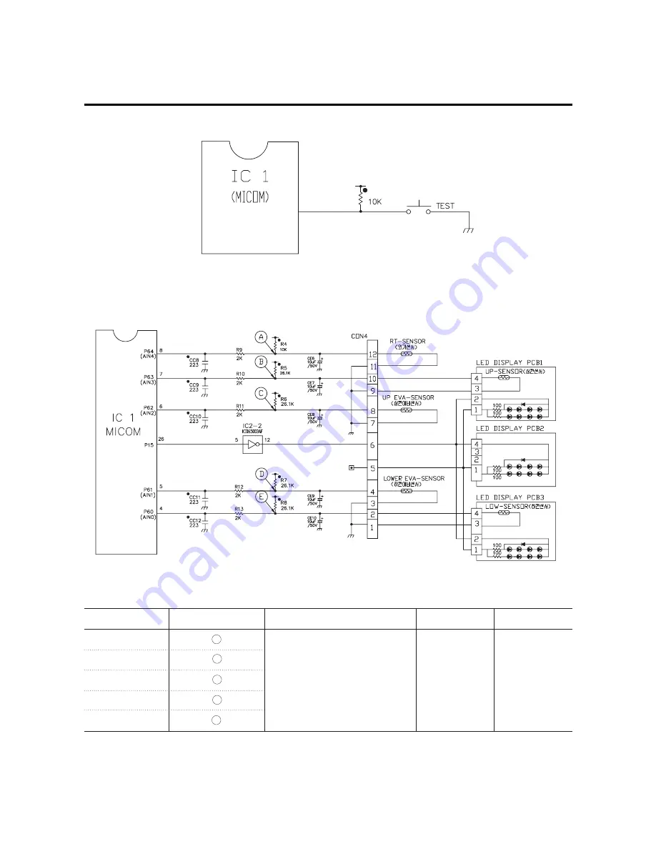
6-2-6. Switch Input Circuit
Input Circuit is to sense a TEST-S/W signal for refrigerator inspection.
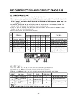
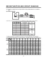
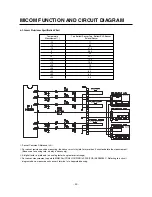
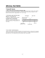
6-2-7. Temperature Sensing Circuit
This circuit consists of top/bottom sensor, top EVA/bottom EVA sensor for controlling top/bottom parts’ storage/maturing
temperature, and an exterior temperature sensor. Each sensor’s SHORT and OPEN condition is as followed.
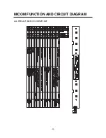
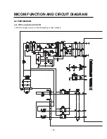
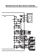
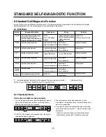
MICOM FUNCTION AND CIRCUIT DIAGRAM
- 27 -
P11
20
R18
Sensor
Check Point
Normal (-30
~50
)
SHORT
OPEN
Exterior Sensor
POINT A Voltage
Top Sensor
POINT B Voltage
Bottom Sensor
POINT E Voltage
0.5 V~4.5 V
0 V
5 V
Top EVA Sensor
POINT C Voltage
Bottom EVA Sensor
POINT D Voltage
Summary of Contents for GC-W061 series
Page 8: ... 8 3 Exterior 3 1 Exterior GC W061 EXTERIOR ...
Page 9: ...GC W101 EXTERIOR 9 ...
Page 10: ...EXTERIOR 10 ...
Page 11: ...GC W141 EXTERIOR 11 ...
Page 12: ...EXTERIOR 12 ...
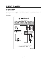
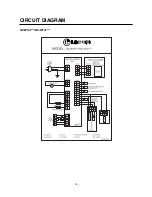
Page 14: ...CIRCUIT DIAGRAM 14 GC W101 GC W141 ...
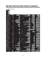
Page 32: ...6 4 2 Replacement Parts List MICOM FUNCTION AND CIRCUIT DIAGRAM 32 ...
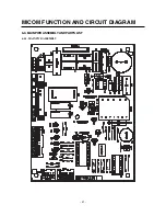
Page 33: ...6 4 3 PWB ASS Y DISPLAY AND PARTS LIST MICOM FUNCTION AND CIRCUIT DIAGRAM 33 ...
Page 35: ...MICOM FUNCTION AND CIRCUIT DIAGRAM 35 ...