


52
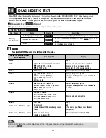
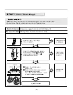
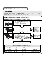
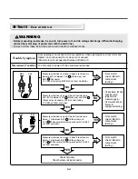
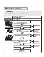
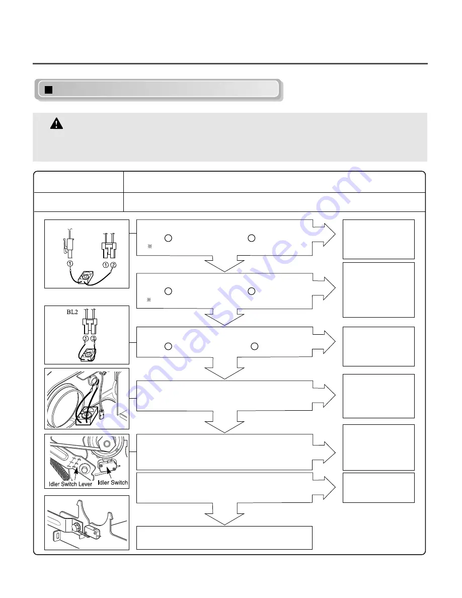
Test 3
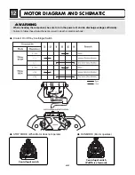
Motor Test
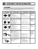
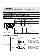
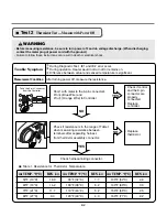
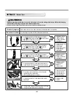
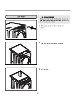
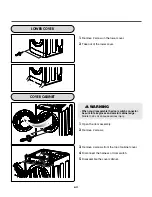
WARNING
• Before measuring resistance, be sure to turn power off, and do voltage discharge. (When discharging,
contact the metal plug of power cord with the earth line.)
• Failure to follow these instructions can result in death or electrical shock.
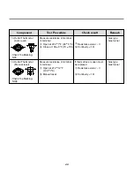
Trouble Symptom
Measurement Condition
Drum does not turn, fan does not blow, and heater does not operate.
Turn the dryer’s power off, then measure resistance.
NO
NO
YES
YES
NO
NO
YES
YES
YES
YES
NO
Is resistance below 3
Ω
between connector
YL3- (White wire) and BL2- (Brown wire)?
Measure while door is closed.
Is resistance below 3
Ω
between Connector
YL3- (White wire) and BL2- Measure
while door is closed.(Yellow wire)?
Is resistance below 3
Ω
between Connector
BL2- (Yellow wire) and BL2- (Brown wire)?
Is resistance below 1
Ω
between terminals of
outlet thermostat attached to blower housing?
Does idle switch attached to motor bracket
operate level by drum belt?
(Not operating lever is normal.)
Is resistance below 1
Ω
between idler switch
terminals?
• Check motor. (Refer to Motor Diagram and Check)
• Check if control connector is contacted.
• Replace control.
(Relay check)
• Check controller
connector.
• Replace control.
(Relay check)
• Check controller
connector.
• Replace outlet
• Thermostat.
(Refer to
component)
• Check idler assembly
• Drum belt cuts off
• Drum belt takes off
from motor pulley.
• Replace idler
switch.
• Check if door frame
presses door
switch knob.
• Check door switch.
• Check harness
connection.
YL3
BL2
1
2
1
2
1
2
Summary of Contents for / GD1329QES
Page 2: ...MARCH 2010 PRINTED IN KOREA P No MFL62119919 ...
Page 46: ...13 CONTROL LAY OUT 45 PWB ASSEMBLY DISPLAY LAY OUT PWB ASSEMBLY LAY OUT ...
Page 69: ...EXPLODED VIEW 19 19 1 1 Control Panel Plate Assembly Coin Type A210 A120 A110 68 ...
Page 70: ...19 1 2 Control Panel Plate Assembly Card Type A210 A120 A117 A110 69 ...


