GHX-308A/616
HYBRID KEY TELEPHONE SYSTEM
Http://suryawardana.com
18
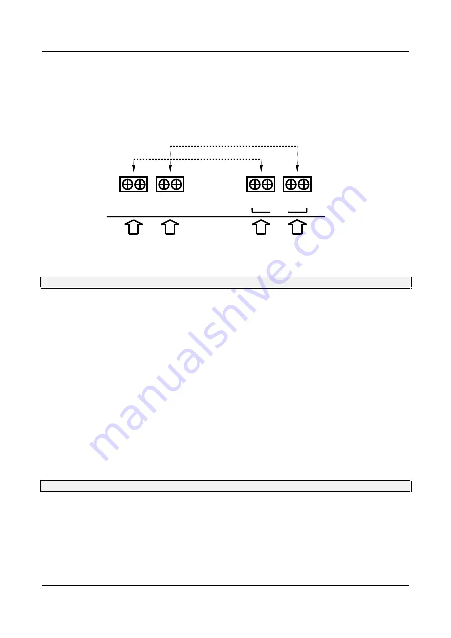
In the event of a commercial power failure without battery back-up, upto 2 CO/PABX lines can be automatically
transferred to single line telephones for emergency communications. When power interrupted, CO 1T/R, 2T/R are
automatically transferred to SLT #106, #107, the corresponding emergency telephone can be used as SLT extension
under normal operation.
CO/PBX Line #1 ?
Transfer to SLT #106 (Connector “S106 T/R” on the MBU)
CO/PBX Line #2 ?
Transfer to SLT #107 (Connector “S107 T/R” on the MBU)
MBU
T R T R
1T 1R 2T 2R
S107 S107
CO
SLT
SLT
LINE1 LINE2
[Figure 3-7] POWER FAILURE TRANSFER CONNECTIONS
3.12 PHONE BOX CONNECTION
The GSX Phone Box is designed to initiate calls to preassigned stations as well as receive intercom calls with handsfree
talkback operation.
The unit should be located in weather protected areas where paging or monitoring is required.
Each phone box is connected to a dedicated key telephone station line cord position.
The connection of Phone Box(es) to the KSU is identical to that of key telephone.
a) The housings separated by inserting a thin, flat-edged tool at the bottom rim of the assembly. By pressing inward
on the recessing tab, the assembly will open.
b) The cable is routed through the cable entry holes provided on the bottom plate and is connected to the screw
terminal strip on the upper housing. Four screw terminals are identified by wire color on the silk-screened printed
circuit board to correcspond with the wiring sequence at the MDF.
c) The slack wiring should be pulled back through the bottom mounting plate and the top housing snapped shut.
d) The bottom plate of the Phone Box assembly is fastened to the wall by mounting with NO.8 or larger pan head
screws.
3.13 LOUD BELL CONTROL CONNECTION
The GHX-308A system provides relay contact closure to activate optional signaling equipment during incoming CO/PABX
line and intercom ringing.
The stations for Loud Bell Control are selected as part of system programming (Admin program, FLASH 23). Connect the
Loud Bell to FR 1T/1R, 2T/2R terminal of free relay on the MBU.
Regular electrical specification of the free relay is 120VAC, 500mA(24VDC 1A).
See [Figure 3-8] Miscellaneous Wiring.


