2-42
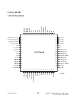
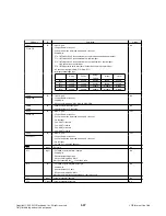
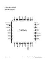
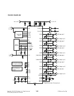
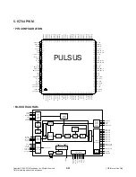
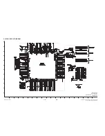
5. IC704 PWM
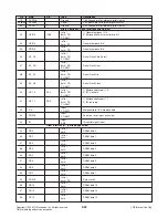
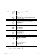
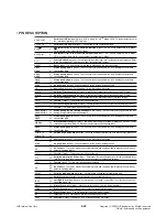
• PIN DESCRIPTION
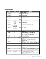
Name
Pin NO.
Type
Description
Power and Ground
PLL_AVDD 6
Analog
Power
PLL analog power supply.
PLL_AVSS 8
Analog
Ground
PLL analog ground.
PLL_DVDD 3 PLL
Power
PLL digital power supply.
PLL_DVSS 2 PLL
Ground
PLL digital ground.
DVDD
13, 34, 42,
66, 80, 91
Power Core
power
supply.
DVSS 14,
35,
43,
63, 81, 92
Ground
Core digital ground.
IO_VDD 4,
10, 22, 29, 39, 47,
56, 65, 72, 94
Power
I/O power supply. 3.3V Digital power supply.
IO_VSS
1, 5, 7, 9, 21,
28, 38, 44, 50,
53, 57, 60, 64,
69, 73, 85, 95
Ground
I/O digital ground.
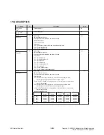
Reset and Clock
/RESET
96
I
H/W reset signal. Active Low Schmitt-Trigger input.
The Schmitt-Trigger input allows a slowly rising input to reset the
chip reliably. The RESET signal must be asserted ‘Low’ during
power up. De-assert ‘High’ for normal operation.
XIN 86
Analog
Crystal Oscillator input pin.
XOUT 87
Analog
Crystal Oscillator output pin.
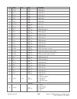
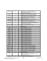
PCM Audio Input/Output Interface
MBCK
11
I/O
PCM bit clock input/output of main 8-channel audio.
User can select the master/slave mode of this signal.
Schmitt-Trigger input.
MLRCK
12
I/O
PCM Word clock (left-right clock) input/output of main 8-channel
audio. User can select the master/slave mode of this signal.
Schmitt-Trigger input.
MSDIN [3:0]
15, 16, 17, 18
I
PCM serial data input of main 8-channel audio.
Schmitt-Trigger input.
SBCK
19
I/O
PCM bit clock input/output of 8-channel audio.
User can select the master/slave mode of this signal.
Schmitt-Trigger input.
SLRCK
20
I/O
PCM word clock (left-right clock) input/output of sub 8-channel
audio. User can select the master/slave mode of this signal.
Schmitt-Trigger input.
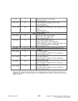
SSDIN [3:0]
23, 24, 25, 26
I/O
PCM serial data input of sub-channel audio.
User can set this sub-channel data input pins to PCM serial data
output pins. See the Control Register Description part.
Schmitt-Trigger input
Copyright © 2009 LG Electronics. Inc. All right reserved.
Only for training and service purposes
LGE Internal Use Only


