4-6
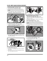
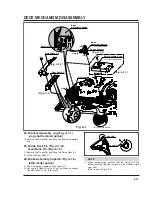
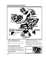
(1) Place the Spring Lever S/W of the above (No.1) as
original position.
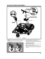
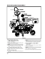
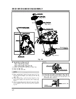
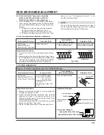
8. Arm Assembly Cleaner(Fig. A-3-1)
1) Break away the (A) part shown above Fig. A-3-1 from the
Embossing of the Chassis in the clockwise direction and
lift up the Arm Assembly Cleaner.
9. Head F/E (Fig. A-3-2)
1) Unhook the two Hooks (H1) on the back side of the
Chassis and lift up the Head F/E.
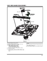
10. Base Assembly A/C Head (Fig. A-3-3)
1) Remove the Screw (S5) and lift up the Base Assembly
A/C Head.
NOTE
DECK MECHANISM DISASSEMBLY
( H1)
Head F/E
Arm Assembly
Cleaner
(A)
(S5)
Base Assembly A/C Head
(For Jog Shuttle Models)
Fig. A-3
(Fig. A-3-1)
(Fig. A-3-3)
(Fig. A-3-2)
Spring
Lever S/W
(H5)
(H5)
Summary of Contents for KB-14P2B
Page 22: ...3 7 BLOCK DIAGRAM ...
Page 23: ...VCD BLOCK DIAGRAM 3 8 ...
Page 24: ...VIDEO AUDIO BLOCK DIAGRAM 3 9 ...
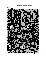
Page 32: ...3 17 PRINTED CIRCUIT BOARD MAIN ...
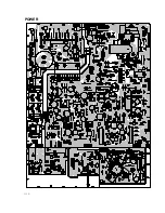
Page 33: ...3 18 POWER ...
Page 79: ...PB A REC A PB V REC V P No 3854VA0070A S Date 2001 02 10 CIRCUIT DIAGRAM OF MV 995B ...


