4-8
DECK MECHANISM DISASSEMBLY
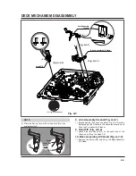
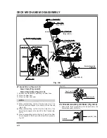
(D)
(C)
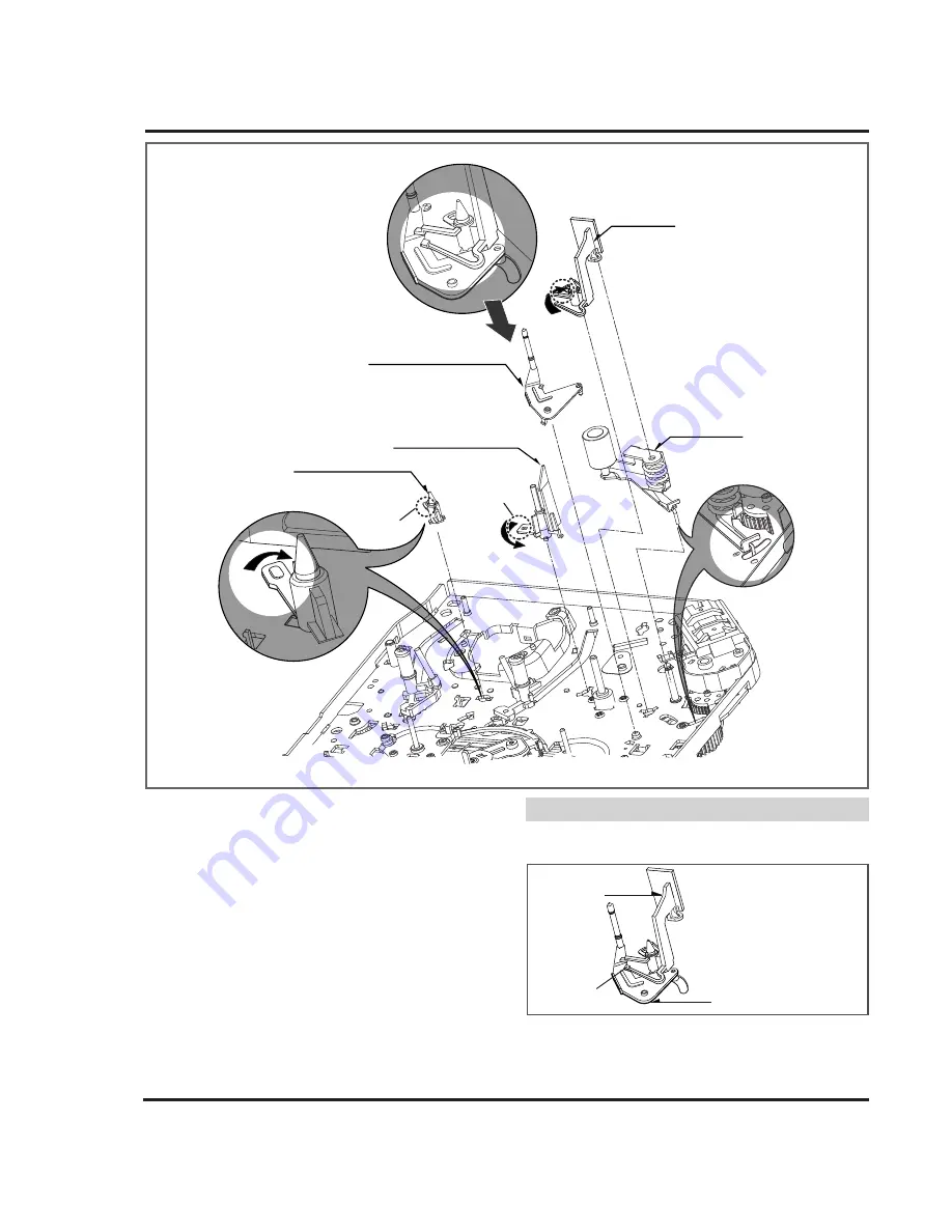
Opener Lid
Arm Assembly T/up
Base Assembly P4
Support CST
Arm
Assembly
Pinch
(B)
(A)
Fig. A-5
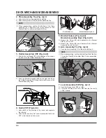
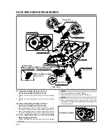
15. Support CST (Fig. A-5-1)
1) Break away the (A) part shown above Fig. A-5-1 from the
Embossing of the Chassis in the clockwise direction, and
lift up the Support CST.
16. Base Assembly P4 (Fig. A-5-2)
1) Break away the (B) part shown above Fig. A-5-2 from the
Embossing of the Chassis in the counterclockwise direc-
tion and lift up the Base Assembly P4.
17. Opener Lid (Fig. A-5-3)
1) Break away the (C) Part of the Opener Lid from the
Embossing of the Chassis in the Clockwise direction and
lift up the Opener Lid.
18. Arm Assembly T/up (Fig. A-5-4)
1) Just lift up the Arm Assembly T/UP.
(1) When reassembling, confirm the opener lid is placed on
the Hook(H1) of the Arm Assembly T/UP as below figure.
19. Arm Assembly Pinch (Fig. A-5-5)
1) Lift up the Arm Assembly Pinch.
NOTE
(H1)
Opener Lid
Arm Assembly T/up
(Fig. A-5-3)
(Fig. A-5-4)
(Fig. A-5-1)
(Fig. A-5-2)
(Fig. A-5-5)
Summary of Contents for KB-14P2B
Page 22: ...3 7 BLOCK DIAGRAM ...
Page 23: ...VCD BLOCK DIAGRAM 3 8 ...
Page 24: ...VIDEO AUDIO BLOCK DIAGRAM 3 9 ...
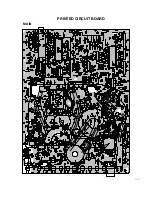
Page 32: ...3 17 PRINTED CIRCUIT BOARD MAIN ...
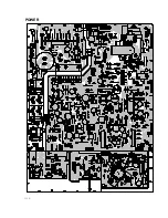
Page 33: ...3 18 POWER ...
Page 79: ...PB A REC A PB V REC V P No 3854VA0070A S Date 2001 02 10 CIRCUIT DIAGRAM OF MV 995B ...


