4-10
DECK MECHANISM DISASSEMBLY
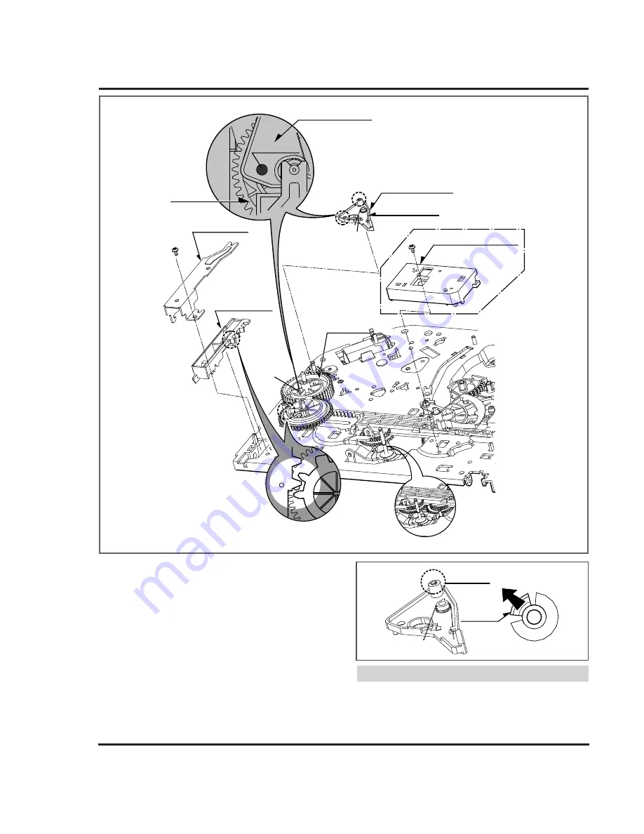
Brake
Assembly Capstan
Hole (A)+(B)
(H2)
(S4)
Gear Cam
Guide Rack F/L
(S4)
Gear Rack F/L
Gear Cam
Hole (B)
(H1)
Hole (A)
Barke
Assembly Capstan
(For Jog Shuttle Models)
(For 4HD Models)
Barke Assembly Jog
Spring Capstan
(For Jog Shuttle Models)
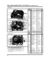
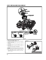
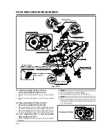
Fig. A-7
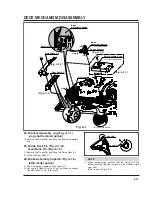
24. Bracket Assembly Jog (Fig. A-7-1)
(Jog shuttle model option)
1) Remove the Screw(S4) and lift up the Bracket Assembly
Jog.
25. Guide Rack F/L (Fig. A-7-2)/
Gear Rack F/L (Fig. A-7-3)
1) Remove the Screw(S4) and lift up the Guide Rack F/L.
2) Lift up the Gear Rack F/L.
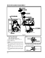
26. Brake Assembly Capstan (Fig. A-7-4)
(4HD model option)
1) Hook the Spring Capstan on the Hook(H1).
2) Unhook the Hook(H2) and lift up the Brake Assembly
Capstan.(Refer to Fig. to the right)
(1) When reassembling, confirm that the Hole(A) of the
Brake Assembly Capstan is aligned to the Hole(B) of the
Gear Cam.
(Refer to above Fig. A-7-4).
NOTE
Hook(H2)
Hook(H2)
(Fig. A-7-4)
(Fig. A-7-1)
(Fig. A-7-2)
(Fig. A-7-3)
Summary of Contents for KB-14P2B
Page 22: ...3 7 BLOCK DIAGRAM ...
Page 23: ...VCD BLOCK DIAGRAM 3 8 ...
Page 24: ...VIDEO AUDIO BLOCK DIAGRAM 3 9 ...
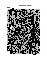
Page 32: ...3 17 PRINTED CIRCUIT BOARD MAIN ...
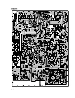
Page 33: ...3 18 POWER ...
Page 79: ...PB A REC A PB V REC V P No 3854VA0070A S Date 2001 02 10 CIRCUIT DIAGRAM OF MV 995B ...

