1-8
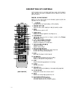
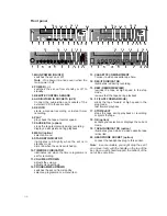
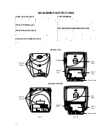
1. MAIN POWER (ON/OFF)
switches the set on or off.
Note : One power line lives even when the
main power is off.
2. POWER (
r
-
I
)
switches the set on from standby or off to
standby.
3. REMOTE CONTROL SENSOR
4. AUDIO/VIDEO IN SOCKETS (AV2)
Connect the audio/video out sockets of the
external VCR to these sockets.
5. REC/ITR
starts a manual recording or instant timer
recording.
6. PLAY
plays back the tape at normal speed.
7. PAUSE/STILL (option)
stops the tape temporarily during recording.
displays a still picture during playback.
8. MENU (option)
selects a menu.
9. STANDBY INDICATOR
illuminates red brightly when the set is in
standby mode.
dims red when the set is switched on.
10. TIMER REC INDICATOR
illuminates red when the timer programme is
set for recording.
11. VOLUME UP/DOWN
adjusts the volume.
adjusts menu settings.
12. PROGRAMME UP/DOWN
switches the set on from standby.
selects a programme or a menu item.
13. CASSETTE COMPARTMENT
To insert a video cassette tape here.
14. REC/ITR INDICATOR
illuminates red during recording.
15. REW (REWIND/REVIEW)
rewinds the tape at high speed in the stop
mode.
reviews fast the tape during playback.
16. FF (FAST FORWARD/CUE)
winds the tape forward at high speed in the
stop mode.
fast forward playback.
17. STOP/EJECT
stops the tape during playback or recording
or ejects the tape.
18. OK (option)
accepts your selection or displays the current
mode.
19. TAPE-IN INDICATOR (option)
illuminates green while a video cassette tape
is inserted.
20. HEADPHONE SOCKET (option)
connect the headphone plug to this socket.
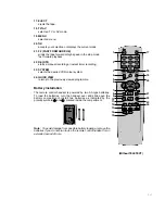
Note : In some models, you might drop the set if
you move it only with the handle on the top of the
set. So you can should support the bottom of the
set at the same time.
Front panel
AV2
ON/OFF
VOL
PR
REC/ITR REW/
PLAY
FF/
P/STILL STOP/EJECT MENU
OK
VIDEO- IN -AUDIO
STAND-BY TAPE-IN TIMER REC
,
,
,,,
,
,,,,,
,,
,,,,,,
,,
,,,,,,,,
,,,
,,,,,,,,,,
,,,,
,,,,,,,,,,,,
,,,,
,,,,,,,,,,,,,
,,,,,
,,,,,,,,,,,,,,,
,,,,,
,,,,,,,,,,,,,,,
,,,,
,,,,,,,,,,,,,,
,,,
,,,,,,,,,,,,,,
,
,,,,,,,,,,,,
,,,,,,,,,,
,,,,,,,,
,,,,,
,,,
REC/iTR REW/
PLAY
FF/
P/STILL STOP/EJECT MENU
OK
VOL
PR
STAND-BY
TAPE-IN
TMER REC
ON/OFF
AV2
VIDEO- IN -AUDIO
20
20
4
14
13
15 16
17
19
18
1
3
5
6
7
8
9 10 11 12
2
4
ON/OFF
/
VOL
PR
STOP/EJECT REW/
PLAY
FF/
REC/ITR
AV2
AUDIO
VIDEO
H/P
REC TIMER REC STAND-BY
IN
13
15
16
10
4
3
1
11
12
17
6
5
14
9
20
2
ON/OFF
VOL
PR
STOP/EJECT REW/
PLAY
FF/
REC/ITR
REC TIMER-REC STAND-BY
13
15
16
10
3
1
11
12
17
6
5
14
9 20
2
14
13
15
16
17
19
18
1
3
5
6
7
8
9 10 11 12
2
4
Summary of Contents for KB-14P2B
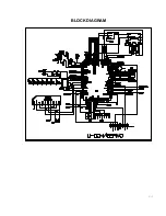
Page 22: ...3 7 BLOCK DIAGRAM ...
Page 23: ...VCD BLOCK DIAGRAM 3 8 ...
Page 24: ...VIDEO AUDIO BLOCK DIAGRAM 3 9 ...
Page 32: ...3 17 PRINTED CIRCUIT BOARD MAIN ...
Page 33: ...3 18 POWER ...
Page 79: ...PB A REC A PB V REC V P No 3854VA0070A S Date 2001 02 10 CIRCUIT DIAGRAM OF MV 995B ...


